Effective
10
/00
Page 23
IL 33-K2C-3
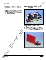
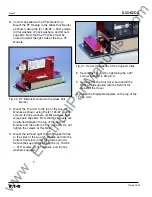
STEP 10: INSTALLING THE TRIP UNIT ON THE
BREAKER
F.
Assure that the area under the Breaker Plat-
form where the holes will be drilled is clear,
then drill two (2) 0.166" diameter holes where
marked.
G. Remove the left hand Mounting Bracket from
the Trip Unit Assembly. Install the Mounting
Bracket on the Breaker Platform using the (2)
.190-18 × .500" thread cutting screws (2) lock
washers, and (2) flat washers supplied.
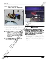
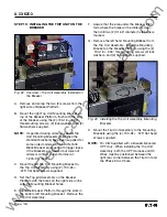
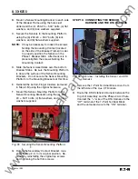
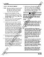
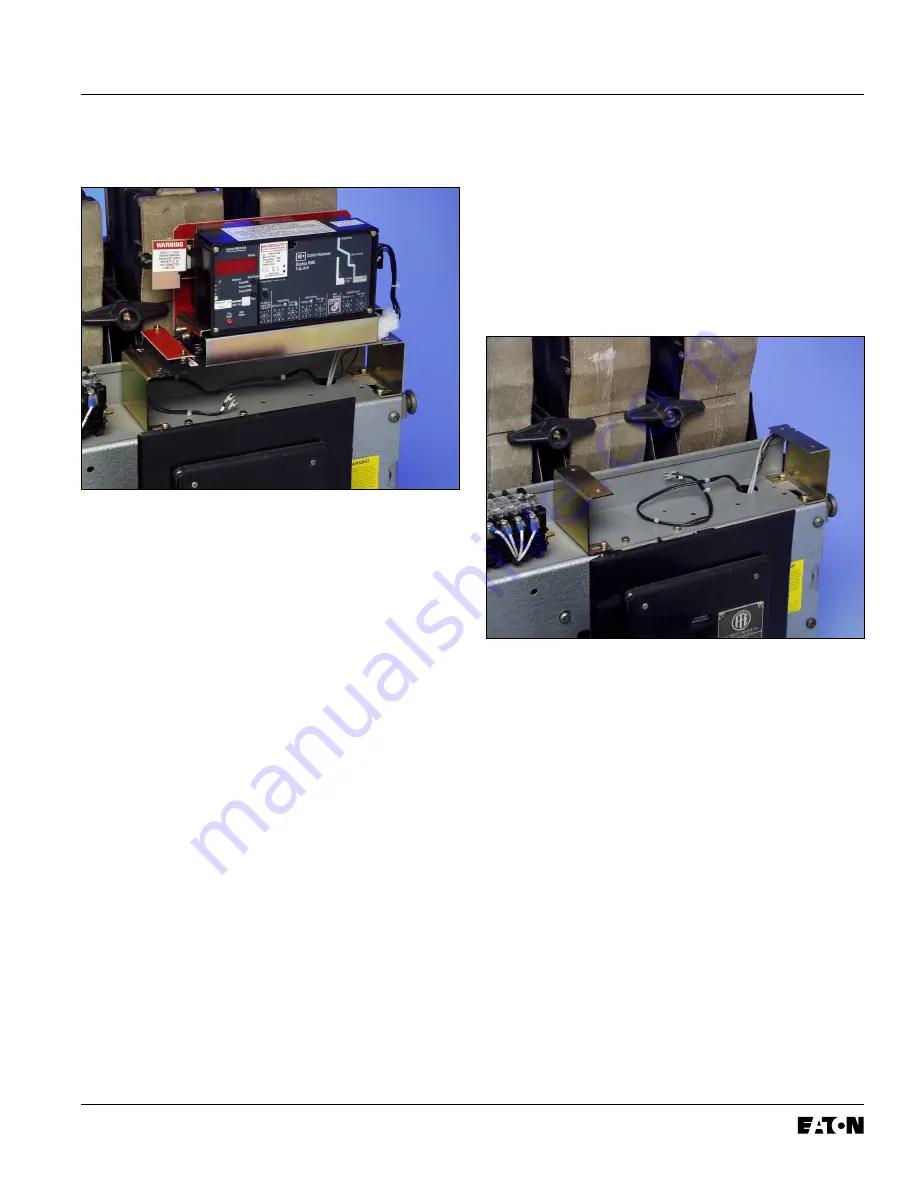
Fig. 42 Overview – Trip Unit Assembly Installed on
the Breaker
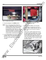
A. Remove and scrap the two (2) screws from the
right side of Breaker Platform.
B. Mount the right Trip Unit Mounting Bracket on
top of the Breaker Platform, flush with the end
of the Breaker, using the (2) .190-18 × .500"
thread cutting screws, (2) lock washers, and (2)
flat washers supplied.
NOTE:
If specified during ordering, special Trip
Unit Mounting Brackets (taller then the
standard brackets) have been supplied for
some older models of the KDON-1600
Black Breaker equipped with trigger fuses.
If the Brackets are needed but were not
ordered, contact Cutler-Hammer at:
1-800-937-5487.
C. Mount the left Trip Unit Mounting Bracket to
the Trip Unit Assembly using (2) .190-32 ×
.375" flat head screws supplied.
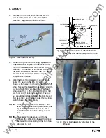
D. Set the Trip Unit Assembly on the Breaker
Platform with the holes on the right side in line
with the Mounting Bracket holes.
E. Mark the Breaker Platform through the slots in
the bottom left Mounting Bracket. Remove the
Trip Unit Assembly.
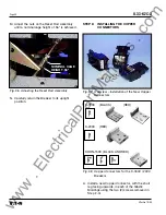
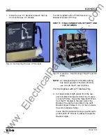
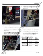
Fig. 43 Installing the Trip Unit Assembly Mounting
Brackets
H. Mount the Trip Unit Assembly to the Mounting
Brackets using the (4) .190-32 × .375" flat head
screws supplied.
NOTE:
For Kits Supplied with a Breaker Mounted
CPT Only:
When installing the Trip Unit
Assembly, both the CPT Harness and HV
Wires must be positioned between the
right rear corner between the Trip Unit and
the Phase 3 Arc Chute.
www
. ElectricalPartManuals
. com


