Effective
10
/00
Page 27
IL 33-K2C-3
ATTENTION:
Before proceeding, it is necessary
to verify which Step 12 is to be
followed for correct installation of
the Sensors. This is done by refer
ring to the Icon(s) with each step.
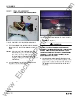
STEP 12: INSTALLING THE SENSORS
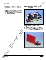
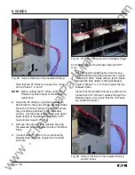
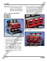
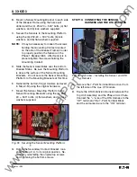
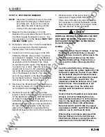
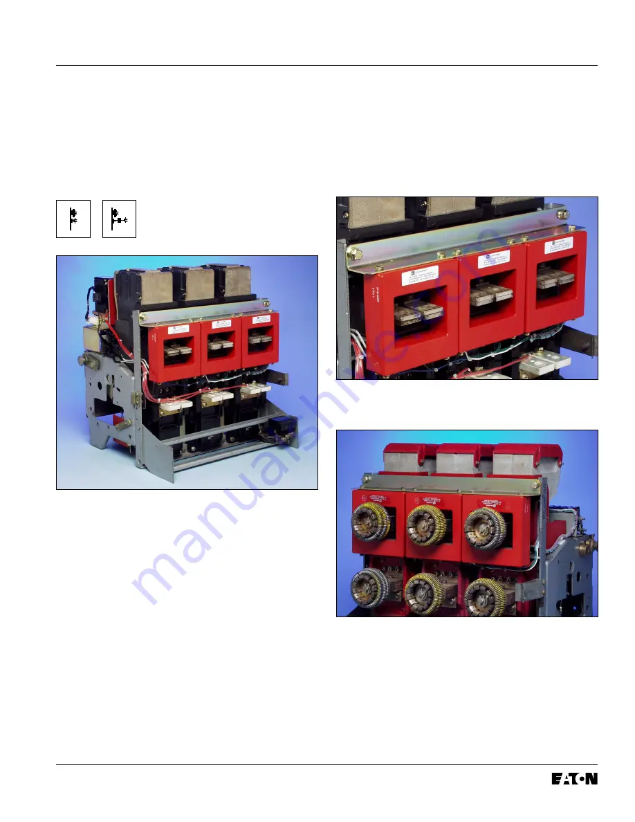
Fig. 50 Overview – Installed Top Mounted Sensors
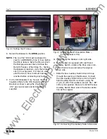
A. Remove the retaining clips and pins securing
the Finger Clusters to the top Breaker Stabs.
Remove the Finger Clusters.
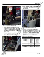
B. Secure the Sensors to the Mounting Angle
using the (6) .250-20 × .500" bolts, (6) lock
washers, and (6) flat washers supplied.
C. Slide the Sensor Assemblies over the top
Breaker Stabs. Do not secure the Sensor
Mounting Angle to the Breaker at this time.
D. Reinstall the top Finger Clusters using the
original hardware.
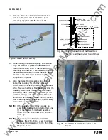
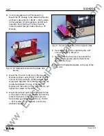
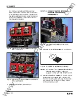
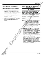
E. Mount the (2) threaded coupling nuts to the top
rear of the Breaker, using the (2) .375-16 ×
.750” bolts, (2) flat washers, and (2) lock wash-
ers supplied. Mount the Sensor Mounting
Angle to the threaded cap nuts, as shown,
using the (2) .375-16 × .750” bolts, (2) flat
washers, and (2) lock washers supplied.
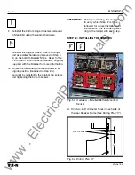
Fig. 51 Securing the Sensor Assembly to the
Breaker
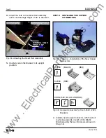
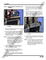
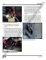
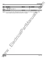
Fig. 52 K-2000 Sensors Installed
www
. ElectricalPartManuals
. com


