background image

Effective 10/00

IL 33-K2C-3

Page 6

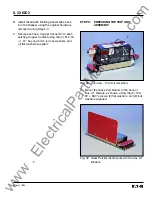
STEP 1:

GENERAL BREAKER PREPARATION

Before attempting to remove the Breaker from the
Cell or perform any Retrofit operation, be sure to
read and understand the Safety Precautions
section of this manual.  In addition, be sure to read
and understand the 

Instructions for the Application

of Digitrip RMS Retrofit Kits on Power Circuit
Breakers

 (Retrofit Application Data – Publication

AD-33-855-2), supplied with the Digitrip Retrofit
Kit.

WARNING

DO NOT ATTEMPT TO INSTALL OR PERFORM
MAINTENANCE ON EQUIPMENT WHILE IT IS
ENERGIZED.  SEVERE PERSONAL INJURY OR
DEATH CAN RESULT FROM CONTACT WITH
ENERGIZED EQUIPMENT.  VERIFY THAT NO
VOLTAGE IS PRESENT BEFORE PROCEEDING.

A. Trip the Breaker and remove it from the Cell.

Move the Breaker to a clean, well-lit work
bench.

NOTE:

It is the responsibility of the Retrofitter to
insure that the Breaker and all original
components are in good condition.  Visu-
ally inspect all Breaker components for
signs of damage or wear.  If any signs of
damage or wear are detected for compo-
nents not included in the Retrofit Kit,
secure the necessary replacement parts
before beginning the Retrofit Process.

The force necessary to trip the Breaker
should not exceed three (3) lbs.

NOTE:

It is the responsibility of the Retrofitter to
insure that the proper, manufacturer’s
recommended crimping tools and termi-
nals are used for each type of connector.
It is also the responsibility of the
Retrofitter to insure that all wire
preparations, connections, strippings,
terminations, and wiring techniques are
performed according to the latest IEEE,
NEC, and / or NEMA industry standards,
specifications, codes, and guidelines.

To begin the Retrofit Process, refer to the compo-
nents list at the end of this manual.  Lay out the
components and hardware according to the steps
outlined.  The parts bags are labeled with the
corresponding step number.  The components and
hardware will be used to complete each step in the
Retrofit Process.

www 

. ElectricalPartManuals 

. com 

Summary of Contents for Digitrip 510 basic

Page 1: ...r isolating a high voltage circuit Follow all lockout and tagging rules of the National Electric Code and all other applicable codes regulations and work rules Do not work on a closed breaker or a breaker with the closing springs charged Trip open the breaker and be sure the stored energy springs are discharged before performing any work The breaker may trip open or the charging springs may discha...

Page 2: ...esting the Breaker 33 Step 16 Mounting the Cell Harness 34 CONTENTS Step 17 Installing the Retrofitted Breaker in the Cell 34 Figures 1 Original Electromechanical Trip Units 7 2 Removing the Glastic Moldings 7 3 Drilling Plan A Front View 8 4 Optional Drilling Plan A 8 5 Drilling Plan B Front View 9 6 Overview DTA Assembly 9 7 Optional DTA Mounting Location 9 8 DTA Mounted to the DTA Mounting Angl...

Page 3: ...bly Mounting Brackets 23 44 Connecting the Aux CT Harness 24 45 Overview Final Routing of the PT and HV Wires 24 46 Correct Position of the Insulated Tubing 25 47 PT Wires Connected to the Breaker Stags 25 48 Correct Position of the Insulated Tubing and HV Fuses 26 49 HV Wires Connected to the Top Breaker Stabs 26 50 Overview Installed Top Mounted Sensors 27 51 Securing the Sensor Assembly to the ...

Page 4: ...hich components are included with the Kit The instructions contained in this manual cover the installation of all levels of Retrofit Kit If the Kit you are installing does not contain a certain component skip the instructions for that component and proceed to the next Throughout the Retrofit process refer to the Torque Tables at the back of this manual for specific torque values If you have any qu...

Page 5: ...r 1 Location Type Location Configuration Kit Code Non Fused K 1600 Black Top Rectangular None N A K1C K 1600 Red Top Rectangular None N A K2C K 2000 Red Top Round None N A K2D Top Mounted Horizontal and Vertical Fused KDON Black 2 Bottom Rectangular Top Horizontal K6C 1600 or Vertical KDON Red Bottom Rectangular Top Horizontal K4C 1600 or Vertical KDON Red Bottom Round Top Horizontal K7C 1600 or V...

Page 6: ...ondition Visu ally inspect all Breaker components for signs of damage or wear If any signs of damage or wear are detected for compo nents not included in the Retrofit Kit secure the necessary replacement parts before beginning the Retrofit Process The force necessary to trip the Breaker should not exceed three 3 lbs NOTE It is the responsibility of the Retrofitter to insure that the proper manufac...

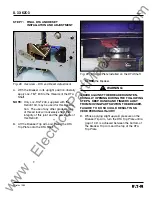
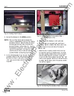
Page 7: ...crews securing each of the three 3 copper pieces to the Breaker Pole Assemblies E Remove the Glastic Moldings with the at tached Electromechanical Trip Units from the Breaker Fig 1 Original Electromechanical Trip Unit A For Breakers equipped with a Secondary Contact Bracket move the back of the Breaker near the edge of the work bench Remove the two 2 screws securing the top of the Second ary Conta...

Page 8: ...for the Sensor Harness can not be drilled where indicated in Drilling Plan A If this is the case with the Breaker Being Retrofitted follow the instructions in Step 3 B B For Use on Some Versions Working from the rear of the Breaker and using a 500 drill bit drill a hole in the left Breaker Angle directly below the top Breaker Cross Rail See Fig 4 This hole will be used later in the Retrofit Proces...

Page 9: ...er in the Retrofit Process when connecting the PT and or HV Wires STEP 4 PREPARING THE DTA ASSEMBLY FOR INSTALLATION Fig 6 Overview DTA Assembly NOTE If an existing Breaker component does not allow the DTA to be mounted on the right side of the Breaker when viewed from the rear of the Breaker a left hand DTA mounting kit is available For details and to acquire the necessary parts contact Cutler Ha...

Page 10: ...DTA Assembly as shown using the 2 164 32 625 screws 4 flat washers 2 lock washers and 2 nuts supplied Note that the non threaded holes in the Mounting Bracket are used to secure the Mounting Bracket to the DTA Assembly Fig 8 DTA Mounted to the DTA Mounting Angle C Connect the DTA Wires to the two 2 top terminals of the 2 Point Terminal Block Con nect the DTA Extension Harness to the two 2 bottom t...

Page 11: ...xtend through the hole in the DTA Reset Arm Fig 13 Overview DTA Assembly installed in the Breaker A Carefully lay the Breaker on its left side B Working from the bottom of the Breaker drill a 312 diameter hole in each of the bottom Breaker Flanges 1 75 from the Breaker Back Plate Insure that no metal shavings fall into the Breaker during the drilling process C Insert the DTA Assembly into the Brea...

Page 12: ...hardware just removed again temporarily mount the DTA Assembly to the Breaker Fig 15 Correct Wiring Harness Position Fig 16 Spacers Installed with the DTA Assembly Return the Breaker to its upright position and verify that there is clearance between the bottom of the DTA Shaft and the work bench If clearance exists tighten the DTA Assembly mounting hardware NOTE If proper clearance can not be achi...

Page 13: ...ngle in Step 4 the Breaker Mounted CPT can not be installed on the DTA Assembly as detailed in the following steps The CPT will have to be mounted either in another location on the Breaker or in the Breaker Cell Alternative mounting of the CPT is the sole responsibility of the Retrofitter NOTE On some versions of the K 1600 2000 Breakers originally supplied with a Breaker Interlock Mechanism the B...

Page 14: ... 164 32 312 pan lock screws and 2 flat washers supplied Fig 20 Bracket Mounted to the CPT Insulation Barrier Fig 21 Identification of the Line and Load Side HV Wires NOTE The Load Side HV Wires are longer than necessary and are cut during the following steps Before cutting the wires insure that sufficient length is left so that the connections can be made to the correct terminals on the CPT C Rout...

Page 15: ... attach a 138 ring terminal to each wire of the HV Wire Attach the HV Wires to the CPT terminals to achieve the required voltage See Table 3 Table 3 CPT Voltage Taps Fig 23 CPT Harness and HV Wires connected to the CPT G Align the holes in the CPT Assembly with the holes in the DTA Assembly as shown Secure the left side of the CPT Mounting Plate to the DTA Mounting Angle as shown using the 1 164 3...

Page 16: ... and 2 flat washers supplied Fig 26 Insulation Plate Mounted to the CPT J Tighten the hardware that secures the DTA Assembly to the Breaker K Attach the appropriate CPT Voltage Label in a clearly visible position on the front of the Breaker Three 3 labels are included with the CPT Kit one 1 for 480 Volt one 1 for 240 Volt and one 1 for 208 Volt systems Fig 27 Supplied CPT Voltage Labels w w w E l ...

Page 17: ... turn the DTA Trip Plate until a gap of 06 is achieved between the bottom of the Breaker Trip Arm and the top of the DTA Trip Plate Fig 28 Overview DTA and Reset Adjustment A With the Breaker in its upright position liberally apply Loc Tite 243 to the threads of the DTA Shaft NOTE Only Loc Tite 243 supplied with the Retrofit Kit may be used for this applica tion The use of any other grade or type ...

Page 18: ... shown using the 2 164 32 312 pan lock screws and 2 flat washers supplied Fig 31 Mounting the DTA Insulation Plate K 2000 Breakers Only G Carefully lay the Breaker on its right side H If the Breaker is equipped with a left hand Auxiliary Switch observe the Drive Link orien tation then remove and scrap the original Drive Link I Slide the new Auxiliary Switch Drive Link up through the opening in the...

Page 19: ...od Assembly and the Auxiliary Switch Drive Link to the Pole Shaft Stop using the 1 250 20 1 25 bolt 4 flat washers and 1 lock nut supplied The lock nut should be installed so that the bolt Reset Rod Assembly and if applicable the Auxiliary Switch Drive Link move freely NOTE If the Auxiliary Switch Drive Link is not used in the Breaker being Retrofitted one 1 of the flat washers should be elimi nat...

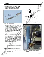
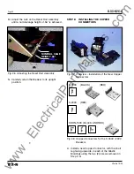
Page 20: ...rs K 1600 BLACK RED K 2000 RED KDON 1600 BLACK AND RED Fig 38 Copper Connectors for the K 1600 2000 Breakers A Install a new Copper Connector with the short leg facing upwards in each of the Glastic Moldings using the two 2 screws removed in Step 2 G Fig 36 Adjusting the Reset Rod Assembly N Carefully return the Breaker to its upright position NOMINAL CAGE HEIGHT 56 w w w E l e c t r i c a l P a r...

Page 21: ...ontact using the 4 312 18 1 12 hex cap bolts 4 lock washers and 4 flat washers supplied STEP 9 PREPARING THE TRIP UNIT ASSEMBLY Fig 38 Overview Trip Unit Assembly A Mount the Glass Poly Barrier to the back of Aux CT Module as shown using the 2 190 32 380 screws 2 flat washers and 2 lock washers supplied Fig 39 Glass Poly Barrier Mounted to the Aux CT Module w w w E l e c t r i c a l P a r t M a n ...

Page 22: ...tall the Cover G Install the Digitrip Nameplate on the top of the Trip Unit Fig 40 PT Module Mounted to the Glass Poly Barrier C Mount the Trip Unit to the top of the Aux CT Module as shown using the 2 190 32 4 00 screws 2 lock washers 2 flat washers and 2 spacers supplied Note that the spacers are positioned between the top of the Aux CT Module and the bottom of the Trip Unit Do not tighten the s...

Page 23: ...ng Brackets taller then the standard brackets have been supplied for some older models of the KDON 1600 Black Breaker equipped with trigger fuses If the Brackets are needed but were not ordered contact Cutler Hammer at 1 800 937 5487 C Mount the left Trip Unit Mounting Bracket to the Trip Unit Assembly using 2 190 32 375 flat head screws supplied D Set the Trip Unit Assembly on the Breaker Platfor...

Page 24: ...use on both the PT and HV Wires For Kits Supplied with a PT Module Only A Cut appropriate length pieces from the sup plied insulated tubing and install one 1 piece on each PT Wire Route the three 3 PT Wires from the PT Module to the right side of the Breaker through the hole drilled in the right Breaker Angle in Steps 3 C or D then towards the bottom Breaker Stabs Insure that the insulated tubing ...

Page 25: ...g Note that the PT Wires are marked for connec tion to Phase 1 2 and 3 NOTE Before cutting the PT Wires verify the Phase Convention used on the Breaker Application B Route the PT Wires to a position suitable for attachment to the proper Phase Breaker Stabs Move the PT Wire markers to a position where they will still be attached to the wires after cutting Cut the wires to length strip an appro pria...

Page 26: ...are longer than necessary and are cut during the following steps Before cutting the wires be sure that sufficient length is left so that the connections can be made to the correct Breaker Stabs F Remove the screws lock washers and nuts that secure the Phase 1 and 2 or 2 and 3 top Breaker Stabs to the Back Plate G Cut the HV Wires to the appropriate length for attachment to the Phase 1 and 2 or 2 a...

Page 27: ... 6 250 20 500 bolts 6 lock washers and 6 flat washers supplied C Slide the Sensor Assemblies over the top Breaker Stabs Do not secure the Sensor Mounting Angle to the Breaker at this time D Reinstall the top Finger Clusters using the original hardware E Mount the 2 threaded coupling nuts to the top rear of the Breaker using the 2 375 16 750 bolts 2 flat washers and 2 lock wash ers supplied Mount t...

Page 28: ...ssociated hardware removed in Step 2 B on the bottom Breaker Stabs Refer to the ITE K 1600 2000 Instruction Manual originally supplied with the Breaker for more information G Rotate the Secondary Contact Bracket to its original position loosened in Step 2 A Secure it by reinstalling the original top screws and tightening the bottom screws Fig 53 Overview Installed Bottom Mounted Sensor A Drill two...

Page 29: ...ing Platform to the Mounting Brackets at this time E Reinstall the bottom Finger Clusters removed in Step 2 B using the original hardware F Mount the Sensor Mounting Platform to the Sensor Mounting Brackets using the 4 250 20 500 bolts 4 flat washers and 4 lock washers supplied STEP 13 CONNECTING THE SENSOR HARNESS AND THE DTA HARNESS Fig 55 Securing the Sensor Mounting Platform G Rotate the Secon...

Page 30: ... Sensor Harness towards the left rear of the Breaker then through the hole drilled in Step 3 A or B Fig 59 Routing of the Sensor Harness E Connect the ring terminals of the Sensor Harness to the Sensors Refer to Section 12 of the Retrofit Application Data supplied with the Retrofit Kit for detailed wiring specifications Depending on the Sensors supplied with the Retrofit Kit the following ratings ...

Page 31: ... Mounting Bracket using the 2 nylon wire clamps and the 2 138 380 thread cutting screws supplied Fig 60 Sensor Harness Connected to the Top Mounted Sensors Fig 61 Sensor Harness Connected to the Bottom Mounted Sensors Fig 62 Overview Connecting the External Harness A Connect the External Harness to the Trip Unit For Kits Supplied with a PT Module Only Refer to Section 7 3 Power Flow Convention of ...

Page 32: ...t least one 1 wire tie to secure the existing wiring harness that was routed below the DTA Assembly earlier in the Retrofit Pro cess to the left side of the Breaker as shown Fig 64 Securing the External Harness C For Kits Supplied with a PT Module Only Connect the PT Harness to the External Harness D For Kits Supplied with an Auxiliary Switch Only Connect the External Harness to the Auxiliary Swit...

Page 33: ...cations For test information specific to the Trip Unit refer to the IL publication supplied with the Retrofit Kit see the Pick List for the IL number F While Section 8 of the Instructions for the Application of Digitrip RMS Retrofit Kits on Power Circuit Breakers provides the informa tion necessary for testing the Breaker please keep the following notes in mind when review ing other sections of th...

Page 34: ... SEVERE PERSONAL INJURY AND OR PROPERTY DAMAGE NOTE It is the responsibility of the Retrofitter to insure proper Breaker Cell fit When racking the Breaker into the Connected position the Retrofitter MUST FOLLOW BOTH the manufacturer s instructions and the customer s safety standards and procedures for racking a Breaker into the Connected position A With the Breaker in the Open position and the spr...

Page 35: ...4 Lock Washer Stl 2 164 32 Nut Hex Stl 2 Aux Switch Kit 4A35899G02 1 Microswitch 1 Mounting Bracket 1 138 32 1 00 Lng Screw 2 138 32 375 Lng Screw 2 138 Flat Washer Stl 8 138 Lock Washer Stl 4 138 32 Nut Hex Stl 4 Step 5 DTA Mounting Parts 4A35899G06 1 Square Spacers 4 250 20 750 Lng Hex Bolt 2 250 Flat Washer Stl 4 250 Lock Washer Stl 2 250 20 Nut Hex Stl 2 Step 6 Breaker Mounted CPT Kit 8259A91G...

Page 36: ...3 3 K 1600 Black Kits Copper Connector K 1600 Red 8259A13G04 3 K 1600 Red Kits Copper Connector K 2000 Red 8259A13G05 3 K 2000 Red Kits Insulation Plate 1 Mounting Bracket 1 164 32 625 Lng Screw 2 164 32 312 Lng Screw Pan Lock 2 164 Flat Washer Stl 6 164 Lock Washer Stl 2 164 32 Nut Hex Stl 2 Copper Connector KDON 1600 Red 8259A13G06 3 KDON 1600 Red Kits 312 18 1 12 Hex Cap Screw 12 K 1600 Black R...

Page 37: ...Comm Only From Step 13 Step 12 Sensor 3 See Pick List Sensor Mounting Parts 4A35899G10 1 Sensor Mounting Bracket 1 250 20 500 Lng Hex Bolt 6 250 Flat Washer Stl 6 250 Lock Washer Stl 6 375 16 750 Lng Hex Bolt 4 375 Flat Washer Stl 8 375 Lock Washer Stl 4 375 16 Nut Threaded Coupling 2 Step 12 Sensor 3 See Pick List Sensor Mounting Parts 4A35899G11 1 Sensor Mounting Platform 1 Sensor Mounting Brack...

Page 38: ... 380 Lng Screw T C 2 Step 16 Cell Harness 6503C57G__ 1 Except 510 Basic Step 14 Cont NOTE Due to the wide variety of Breakers and multiple functions of the Retrofit components some excess hardware may be left when the Retrofit is complete w w w E l e c t r i c a l P a r t M a n u a l s c o m ...

Page 39: ...12 5 16 18 206 17 2 375 3 8 16 356 29 7 438 7 16 14 572 47 7 500 1 2 13 856 71 3 Decimal Standard Torque Torque Size in Size in lbs ft lbs 250 1 4 20 60 5 312 5 16 18 144 12 375 3 8 16 240 20 500 1 2 13 600 50 Table 5 Torque Values for General Mounting and Screw Size Conversion Table 6 Torque Values for Copper BUS Connectors w w w E l e c t r i c a l P a r t M a n u a l s c o m ...

Page 40: ... Transformer F Rating Plug G HV Wires H Aux CT Harness I Sensor Harness J External Harness K Cell Terminal Block L Aux Switch M PT Module N CPT Harness O DTA Extension Harness P Copper Connectors C B A G K E D M L J F H P N I O Fig 67 Retrofit Components w w w E l e c t r i c a l P a r t M a n u a l s c o m ...

Page 41: ...Effective 10 00 Page 41 IL 33 K2C 3 Notes w w w E l e c t r i c a l P a r t M a n u a l s c o m ...

Page 42: ...Effective 10 00 IL 33 K2C 3 Page 42 Notes w w w E l e c t r i c a l P a r t M a n u a l s c o m ...

Page 43: ...Effective 10 00 Page 43 IL 33 K2C 3 Notes w w w E l e c t r i c a l P a r t M a n u a l s c o m ...

Page 44: ...ecommendations descriptions and safety notations in this document are based on Cutler Hammer s experience and judgement with respect to Retrofitting of Power Breakers This information should not be considered to be all inclusive or covering all contingencies If further information is required Cutler Hammer should be consulted NO WARRANTIES EXPRESSED OR IMPLIED INCLUDING WARRANTIES OF FITNESS FOR A...

Reviews: