13
Instruction Leaflet
IL29C614F
Effective December 2011
Instructions for The Digitrip RMS 310 3-Pole and
4-Pole Trip Unit Installation and Operation with
K-Frame Series C Circuit Breakers
EATON CORPORATION
www.eaton.com
The polarity of the neutral sensor connections (if used) must
agree with equipment assembler’s detailed instructions to
avoid improper operations following apparently correct sim-
ulated test operations. Where a question exists, consult the
specifying engineer and/or equipment assembler.
The grounding points of the system shall be verified to
determine that ground paths do not exist that would
bypass the sensors. The use of high-voltage testers and
resistance bridges may be used.
THERE IS A HAZARD OF ELECTRICAL SHOCK OR
BURN WHENEVER WORKING IN OR AROUND
ELECTRICAL EQUIPMENT. ALWAYS TURN OFF
POWER SUPPLYING BREAKER BEFORE CON-
DUCTING TESTS.
Since the Digitrip RMS 310 Trip Units derive their
operating power from the phase currents, and not
from the neutral current, passing current through
the neutral sensor will not properly test the ground
fault feature.
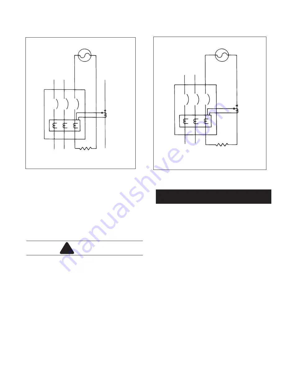
Figure 15-1 Connections for a Trip Test on Ground
Fault.
Load Side
Current-Limiting
Resistor
(If Required)
Line Side
L
C
R
N
Low
Voltage
Source
Polarity
Marks
Figure 15-2 Connections for a No-Trip Test on Ground
Fault for a Four-Wire System.
Load Side
Current-Limiting
Resistor
(If Required)
Line Side
L
C
R
N
Low
Voltage
Source
Polarity
Marks
!
WARNING
NOTICE
When testing the lowest Ground Fault Pick Up (GFPU)
setting, 1
x
I
G
,
t
he indicated connections in Figure
15-4a
must be used. For single phase currents that are
20% of the sensor current rating, the trip unit will not
power up. Therefore, Ground Fault testing cannot be
performed in the usual manner.
The connections displayed in Figure
15-4a
and
15-4b
effectively multiply the power up current by a factor of 3.
With this setup, two of the three currents will cancel and
the third current sh
o
uld cause the breaker to t
ri
p at the
lowest setting.


