Effective
10
/00
IL 33-K2C-3
Page 10
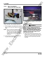
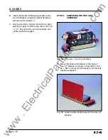
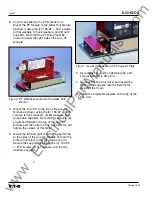
B. Apply Loc-Tite
®
243 to the threads then mount
the DTA and the DTA Bearing Plate Assembly
to the DTA Mounting Angle, as shown, using
the (2) .164-32 × .312" pan lock screws, (2)
.164-32 × .500" pan screws, (2) lock washers,
and (4) flat washers supplied.
NOTE:
Insure that the DTA Shaft moves freely
after mountng. If not, reposition the
mounting hardware.
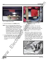
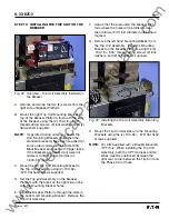
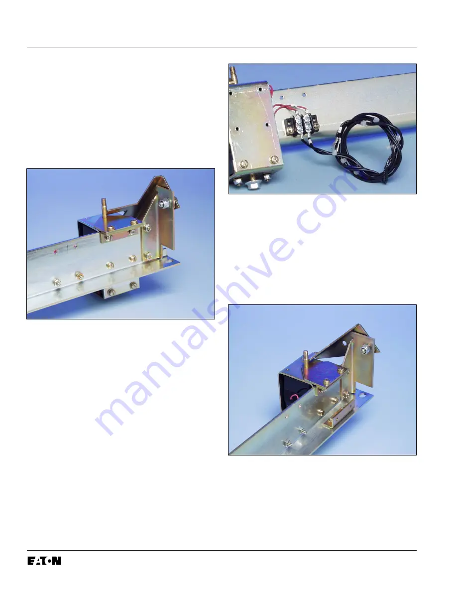
Fig. 9 Connections at the 2-Point Terminal Block
D.
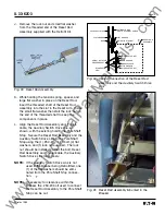
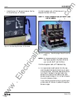
For K-2000 Breakers Only:
Mount the DTA
Insulation Plate Mounting Bracket to the DTA
Assembly, as shown, using the (2) .164-32 ×
.625" screws, (4) flat washers, (2) lock washers,
and (2) nuts supplied. Note that the non-
threaded holes in the Mounting Bracket are
used to secure the Mounting Bracket to the
DTA Assembly.
Fig. 8 DTA Mounted to the DTA Mounting Angle
C. Connect the DTA Wires to the two (2) top
terminals of the 2-Point Terminal Block. Con-
nect the DTA Extension Harness to the two (2)
bottom terminals of the 2-Point Terminal Block.
Connect the “+” wire to the same terminal as
the “+” wire from the DTA. Connect the
unmarked wire to the same terminal as the
unmarked wire from the DTA.
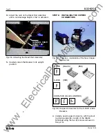
Fig.10
Location of the DTA Insulation Plate
Mounting Bracket
www
. ElectricalPartManuals
. com


