Effective
10
/00
IL 33-K2C-3
Page 12
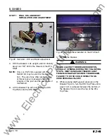
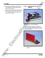
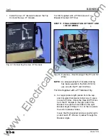
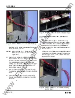
Fig. 14 Installing the DTA Assembly
D. Temporarily mount the DTA Assembly on the
inside of the bottom Breaker Flanges using the
(2) .250-20 × .750" bolts, (4) flat washers, (2)
lock washers, and (2) nuts supplied. Note that
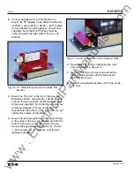
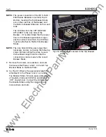
the existing wiring harness must be below the
DTA Assembly.
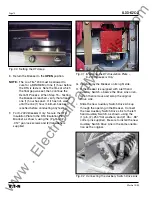
E. Return the Breaker to its upright position.
Verify that there is clearance between the
bottom of the DTA Shaft and the work bench.
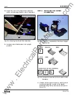
If not, turn the Breaker back on its side, re-
move the mounting hardware securing the DTA
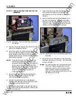
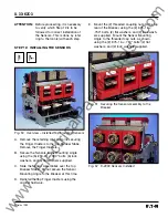
Assembly to the Breaker. Use one (1) or two
(2) of the supplied spacers on each side, as
required, to raise the DTA Assembly. Using the
hardware just removed, again temporarily
mount the DTA Assembly to the Breaker.
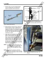
Fig. 15 Correct Wiring Harness Position
Fig. 16 Spacers Installed with the DTA Assembly
Return the Breaker to its upright position and
verify that there is clearance between the
bottom of the DTA Shaft and the work bench.
If clearance exists, tighten the DTA Assembly
mounting hardware.
NOTE:
If proper clearance can not be achieved
by using the spacers provided, or if proper
Trip and Reset functioning can not be
achieved with the spacers installed, the
DTA Shaft may be carefully cut to provide
the proper clearance.
For Kits Supplied with a Breaker Mounted CPT
Only:
Do not tighten the DTA Assembly mount-
ing hardware at this time. This hardware will be
tightened after the Breaker Mounted CPT is
installed in Step 6.
SPACERS
www
. ElectricalPartManuals
. com


