Effective
10
/00
IL 33-K2C-3
Page 18
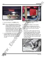
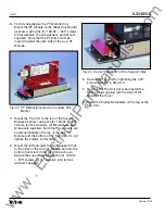
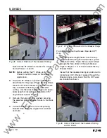
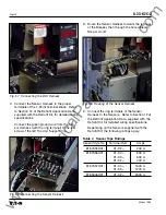
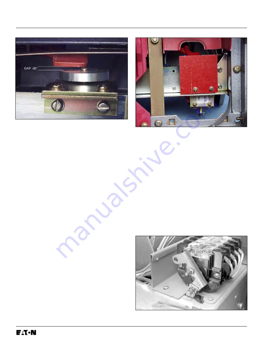
Fig. 30 Setting the DTA Gap
E. Return the Breaker to the
OPEN
position.
NOTE:
The Loc-Tite
®
243 must be allowed to
cure for a MINIMUM of one (1) hour before
the DTA is tested. Note the time at which
the final gap was set, then continue the
Retrofit Process. When Step 15 – Testing
the Breaker is reached, verify that at least
one (1) hour has past. If it has not, wait
until the one (1) hour minimum has been
reached before conducting any testing.
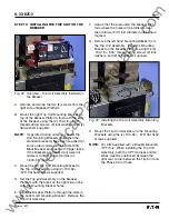
F.
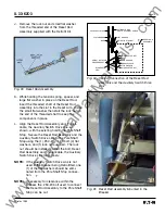
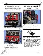
For K-2000 Breakers Only:
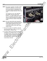
Secure the DTA
Insulation Plate to the DTA Insulation Plate
Bracket, as shown, using the (2) .164-32 ×
.312" pan lock screws and (2) flat washers
supplied.
Fig. 31 Mounting the DTA Insulation Plate –
K-2000 Breakers Only
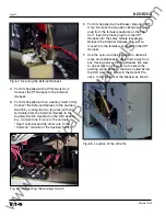
G. Carefully lay the Breaker on its right side.
H. If the Breaker is equipped with a left hand
Auxiliary Switch, observe the Drive Link orien-
tation then remove and scrap the original
Drive Link.
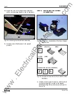
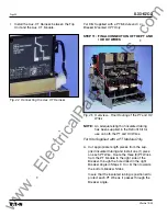
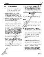
I.
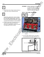
Slide the new Auxiliary Switch Drive Link up
through the opening in the Breaker. Connect
the new Auxiliary Switch Drive Link to the left
hand Auxiliary Switch, as shown, using the
(1) pin, (2) .250" flat washers, and (2) .06 × .88"
cotter pins supplied. Be sure to install the new
Auxiliary Switch Drive Link in the same orienta-
tion as the original.
Fig. 32 Connecting the Auxiliary Switch Drive Link
www
. ElectricalPartManuals
. com


