Effective
10
/00
Page 25
IL 33-K2C-3
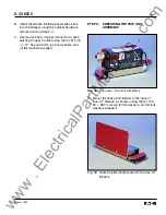
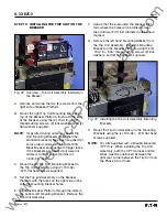
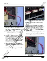
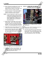
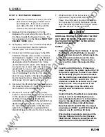
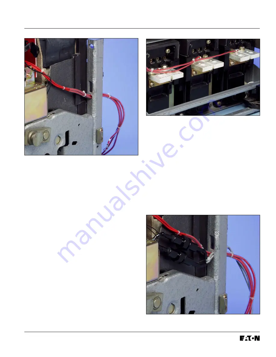
Fig. 47 PT Wires Connected to the Breaker Stags
For Kits Supplied with a Breaker Mounted CPT
Only.
E. Cut appropriate length pieces from the sup-
plied insulated tubing and install one (1) piece
on each HV Wire. Route the two (2) HV Wires
through the hole drilled in the right Breaker
Angle in Steps 3 C or D, then towards the top
Breaker Stabs.
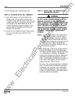
Insure that the insulated tubing is positioned to
protect each HV Wire as it passes through the
Breaker Angle. Also insure that the HV Fuses
are located as shown.
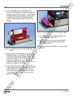
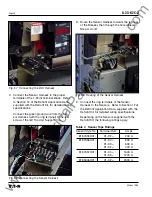
Fig. 46 Correct Position of the Insulated Tubing
Note that the PT Wires are marked for connec-
tion to Phase 1, 2, and 3.
NOTE:
Before cutting the PT Wires, verify the
Phase Convention used on the Breaker
Application.
B. Route the PT Wires to a position suitable for
attachment to the proper Phase Breaker Stabs.
Move the PT Wire markers to a position where
they will still be attached to the wires after
cutting. Cut the wires to length, strip an appro-
priate length of insulation, and install a .375"
ring terminal to each PT Wire.
C. Remove the nuts and lock washers securing
the selected bottom Breaker Stabs to the Back
Plate.
D. Connect each PT Wire to its corresponding
Breaker Stab using the original lock washers
and nuts.
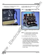
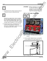
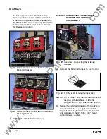
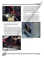
Fig. 48 Correct Position of the Insulated Tubing
and HV Fuses
www
. ElectricalPartManuals
. com


