Effective
10
/00
IL 33-K2C-3
Page 26
NOTE:
The power convention of the ITE K-1600 /
2000 Series Breakers is normally
Top to
Bottom
, meaning the Top Breaker Stabs
are on the
Line Sid
e of the Breaker and
the Bottom Breaker Stabs are on the
Load
Side
.
The HV Wires from the CPT MUST BE
ATTACHED to the
Line Side
of the
Breaker. If it is determined that the power
flow for the Breaker application is oppo-
site the normal convention, the HV Wires
must be attached to the Bottom Breaker
Stabs.
NOTE:
The
Line Side
HV Wires are longer than
necessary and are cut during the following
steps. Before cutting the wires, be sure
that sufficient length is left so that the
connections can be made to the correct
Breaker Stabs.
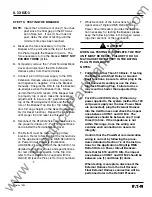
F.
Remove the screws, lock washers, and nuts
that secure the Phase 1 and 2, or 2 and 3 top
Breaker Stabs to the Back Plate.
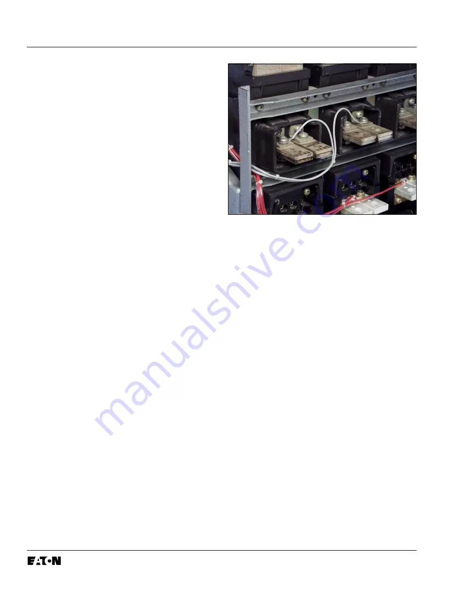
G. Cut the HV Wires to the appropriate length for
attachment to the Phase 1 and 2, or 2 and 3
Top Breaker Stabs. Strip an appropriate length
of insulation from each HV Wire and attach a
.375" ring terminal. Connect the HV Wires to
the Breaker Stabs using the original screws,
lock washers, and nuts.
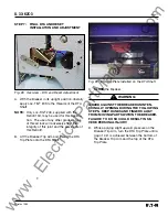
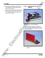
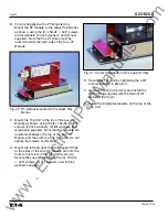
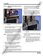
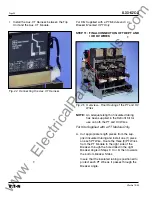
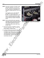
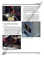
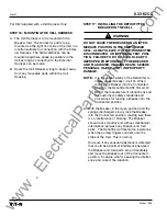
Fig. 49 HV Wires Connected to the Top Breaker
Stabs
www
. ElectricalPartManuals
. com


