Effective
10
/00
Page 31
IL 33-K2C-3
F.
Reinstall the 7-Point Terminal Cover.
STEP 14: CONNECTING THE EXTERNAL
HARNESS AND OPTIONAL
COMPONENTS
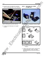
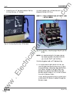
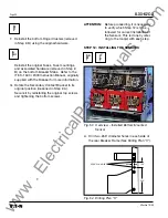
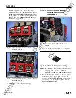
Fig. 63 510 Basic Kit External Harness Plug
NOTE:
For 510 Basic Kits, the External Harness is
the plug pictured above. It is to be
plugged into the right side of the Trip Unit.
B. Secure the External Harness to the two (2) pre-
drilled holes in the upper right corner of the
Trip Unit Mounting Bracket using the (2) nylon
wire clamps and the (2) .138 × .380" thread
cutting screws supplied.
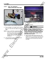
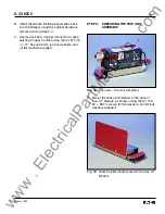
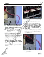
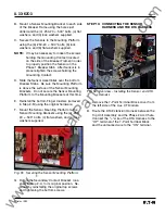
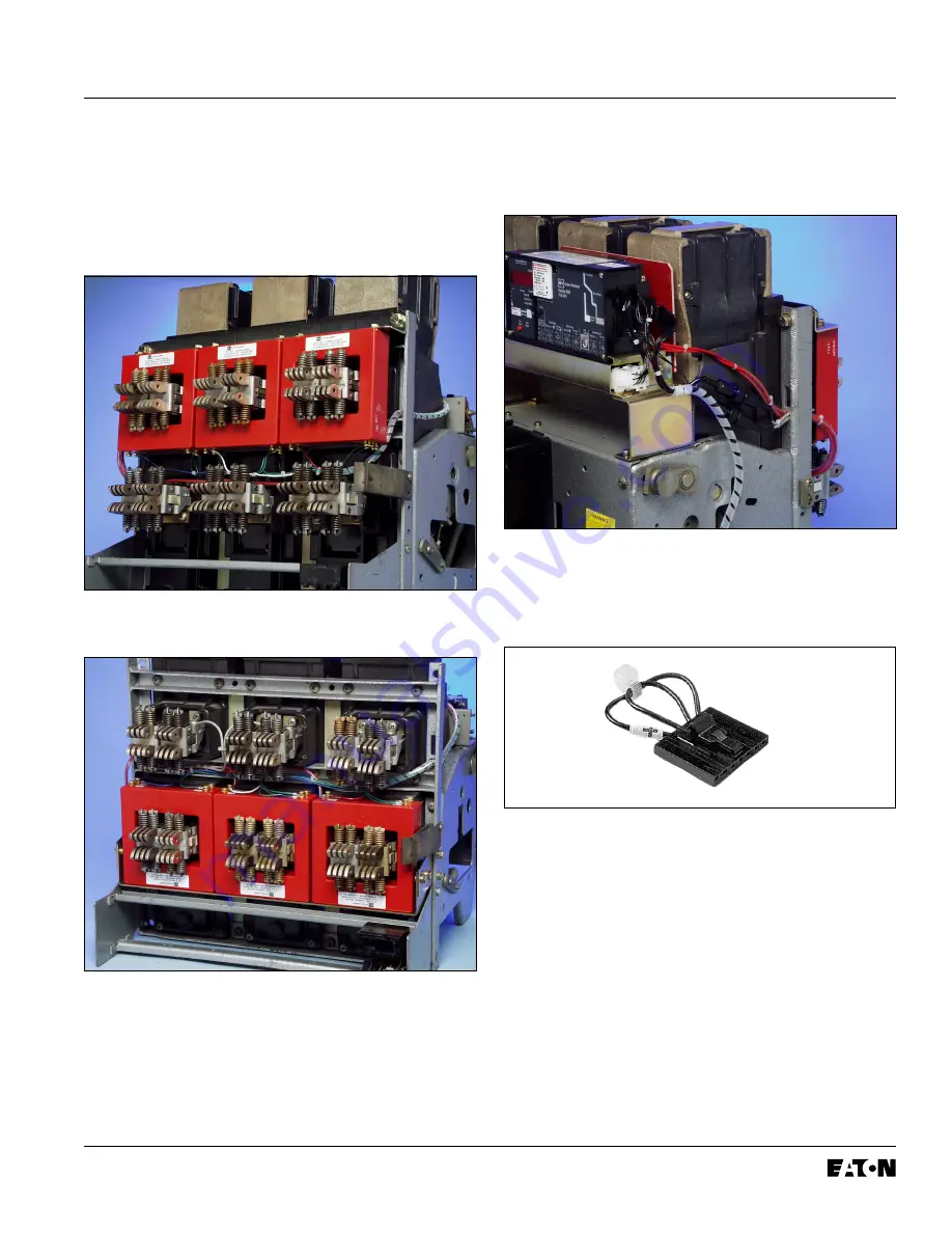
Fig. 60 Sensor Harness Connected to the Top
Mounted Sensors
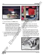
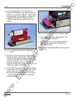
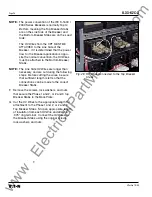
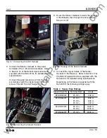
Fig. 61 Sensor Harness Connected to the Bottom
Mounted Sensors
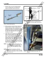
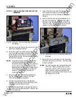
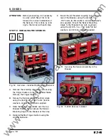
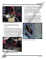
Fig. 62 Overview – Connecting the External
Harness
A. Connect the External Harness to the Trip Unit.
For Kits Supplied with a PT Module Only:
Refer to Section 7-3, Power Flow Convention
of the Retrofit Application Data, supplied with
the Retrofit kit for additional wiring information
and to verify the Phase Convention used on
this Breaker Application.
www
. ElectricalPartManuals
. com

