Effective 10/00
Page 7
IL 33-K2C-3
STEP 2:
PREPARING THE BREAKER FOR
RETROFITTING
Refer to the ITE K-Line Instruction Manual, origi-
nally supplied with the Breaker, to perform the
following procedures.
NOTE:
For all photographs contained within this
manual, an ITE K-1600 Black Breaker
(without blown fuse indicators) was used
as the subject. Depending on the version
and age of the Breaker being Retrofitted,
some components / views may differ from
those depicted in the manual.
Note the orientation of the existing fuses.
Follow the ITE K-1600 / 2000 Instruction
Manual, originally supplied with the Breaker,
and remove the fuses, fuse mountings, and
associated hardware from the bottom Breaker
Stabs. Set all parts aside for reinstallation later
in the Retrofit Process.
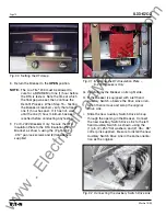
C. Remove the four (4) screws securing each
bottom Glastic Molding to the Breaker.
D. Remove the four (4) screws securing each of
the three (3) copper pieces to the Breaker Pole
Assemblies.
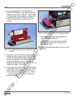
E. Remove the Glastic Moldings, with the at-
tached Electromechanical Trip Units, from the
Breaker.
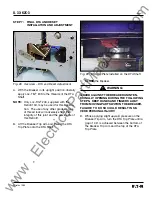
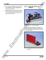
Fig. 1 Original Electromechanical Trip Unit
A. For Breakers equipped with a Secondary
Contact Bracket, move the back of the Breaker
near the edge of the work bench. Remove the
two (2) screws securing the top of the Second-
ary Contact Bracket. Loosen the two (2)
bottom screws then rotate the bracket down
over edge of work bench
B.
Remove the retaining clips then the pins secur-
ing the Finger Clusters to the Bottom Breaker
Stabs. Remove the Finger Clusters. Set all
parts aside for reinstallation later in the Retrofit
Process.
Fig. 2 Removing the Glastic Moldings
F.
Working from the rear of the assembly, remove
the Electromechanical Trip Units by carefully
drilling out the four (4) .190" screws that secure
each Trip Unit to the Molding.
G. Remove the two (2) screws securing the Cop-
per Extensions then remove the Trip Unit from
each Molding.
www
. ElectricalPartManuals
. com


