Effective 10/00
IL 33-K2C-3
Page 8
STEP 3:
DRILLING THE BREAKER ANGLES
A. Working from the rear of the Breaker and using
a .500" drill bit, drill a hole in the left Breaker
Angle (See Drilling Plan “A”). This hole will be
used later in the Retrofit Process when install-
ing the Sensor Harness.
NOTE:
The hole should be drilled slightly below
the Breaker Cross Rail and be located so
as not to interfere with the Lifting Rack
when installed.
After Retrofitting, care should be taken
when installing the Lifting Rack so that
any new wires or harnesses that pass
through the rear Breaker Angles are not
damaged.
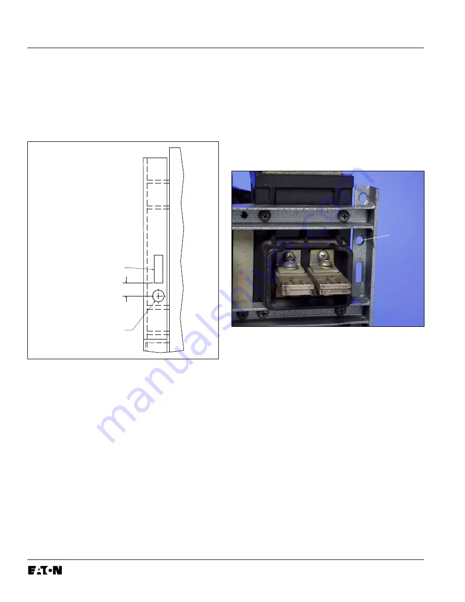
Fig. 3 Drilling Plan “A” - Front View
NOTE:
On some versions of the K-1600 / 2000
Breakers, the hole for the Sensor Harness
can not be drilled where indicated in
Drilling Plan “A”. If this is the case with
the Breaker Being Retrofitted, follow the
instructions in Step 3-B.
B.
For Use on Some Versions:
Working from the
rear of the Breaker and using a .500" drill bit,
drill a hole in the left Breaker Angle, directly
below the top Breaker Cross Rail (See Fig. 4).
This hole will be used later in the Retrofit
Process when installing the Sensor Harness.
Fig. 4 Optional Drilling Plan “A”
For Kits Supplied with a PT Module and / or
Breaker Mounted CPT Only.
C. Working from the rear of the Breaker and using
a .500" drill bit, drill a hole in the right Breaker
Angle (See Drilling Plan “B”). This hole will be
used later in the Retrofit Process when install-
ing the PT and / or HV Wires.
EXISTING SLOT
.50"
.500" DIA. (1) FOR
SENSOR HARNESS
(ALL KITS)
FRONT
VIEW
DRILL
.500"
HOLE
www
. ElectricalPartManuals
. com


