Effective
10
/00
Page 9
IL 33-K2C-3
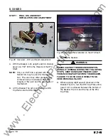
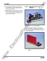
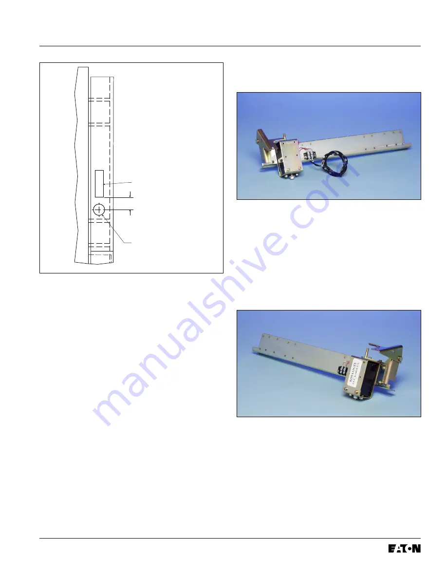
Fig. 5 Drilling Plan “B” - Front View
NOTE:
On some versions of the K-1600 / 2000
Breakers, the hole for the PT and / or HV
Wires can not be drilled where indicated in
Drilling Plan “B”. If this is the case with
the Breaker Being Retrofitted, follow the
instructions in Step 3-D.
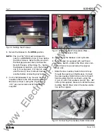
D.
For Use on Some Versions:
Working from the
rear of the Breaker and using a .500" drill bit,
drill a hole in the right Breaker Angle, directly
below the top Breaker Cross Rail (similar to the
hole for the Sensor Harness drilled in Step
3-B). This hole will be used later in the Retrofit
Process when connecting the PT and / or HV
Wires.
STEP 4:
PREPARING THE DTA ASSEMBLY
FOR INSTALLATION
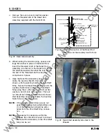
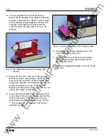
Fig. 6 Overview - DTA Assembly
NOTE:
If an existing Breaker component does not
allow the DTA to be mounted on the right
side of the Breaker (when viewed from the
rear of the Breaker), a left hand DTA
mounting kit is available. For details and
to acquire the necessary parts, contact
Cutler-Hammer at: 1-800-937-5487.
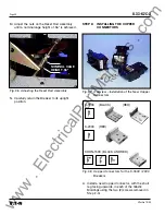
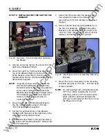
Fig. 7 Optional DTA Mounting Location
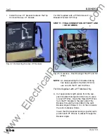
A. Apply Loc-Tite
®
243 to the threads then mount
the DTA Bearing Plate to the DTA Bearing Plate
Mounting Bracket, as shown, using the (2)
.164-32 × .312" pan lock screws and (2) flat
washers supplied.
EXISTING SLOT
.50"
.500" DIA. (1) FOR
HV AND / OR
PT WIRES
FRONT
VIEW
www
. ElectricalPartManuals
. com


