20
External Battery Cabinets
4 .5
External Signaling Cables Connecting
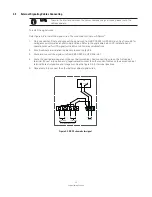
figure 4-8 . EBC Schematic for signal
To install the signal wires:
Refer figure 4-8 to install the signal wires. The wire code is minimum 0.38mm
2
.
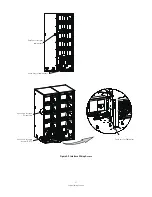
1. Only one cabinet, Route and connect the signal wire from EBC RS232 to UPS Mini-slot. See figure 4-9 for
wiring access information and terminal locations. Refer to the applicable Eaton UPS installation and
operation manual for UPS signal terminal(mini-slot or relay card)locations.
2. If multi-cabinets are installed in parallel, proceed to step 3-5.
3. Route and connect the signal wire from EBC RS232 to UPS Mini-slot.
4. Route the positive and negative to the next battery cabinet. And connect the wire on the first cabinet
terminal (To next (+)positive and (-)negative) and connect the other ends of cables on the second cabinet
terminal(To last (+)positive and (-)negative) .See the figure 4-9 for terminal locations.
5. Repeat setp 4 to connect the other battery cabinet signal wires.
To avoid the interface between the power cables and signal wires, please route the
cables separate.
NOTE
CB
NC
COM
NO
1
2
3
4
+
-
+
-
+
-
To Double Battery Cabinet
To UPS
To Last EBC
To Next EBC
Summary of Contents for Double EBC
Page 1: ...External Battery Cabinets Installation and Operation Manual Eaton UPS Accessories...
Page 2: ......
Page 29: ...23 External Battery Cabinets Notes...
Page 34: ......
Page 35: ......
Page 36: ...614 01726 01...


