13
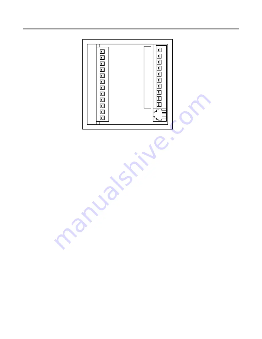
REAR TERMINAL DESCRIPTION
+12 Volt DC
DC Common
DC Common
Ground
No Connection
No Connection
No Connection
Relay 1 N.C.
Relay 1 Com.
Relay 1 N.O.
AC Power Neut
AC Power Hot
Transistor 2 Output
Transistor 1 Output
Input 1
Input 2
Input 3
Input 4
Count Input B
Count Input A
Communi
Communication -
RS-485 communication con-
nector, RJ-11 modular tele-
phone style.
1
12
2
3
4
5
6
7
8
9
10
11
13
14
15
16
17
18
19
20
21
22
4
3
2
1
TERMINAL DESCRIPTIONS
1 - On models 57601 and 57602 this terminal is the +12 VDC
power output. It is used to supply 12 VDC (+/- 25% 100 mA
max) for accessories. DC Common is the negative side of this
supply.
On the model 57600 this terminal is used for the 10-15 VDC
power input. Connect the positive lead of the power supply to
terminal 1 and the negative lead to DC Common.
The DC POWER OUTPUT contains a series Positive Tem-
perature Coefficient (PTC) resistor that undergoes a large
and abrupt increase in resistance when an over-current
condition occurs. This resistance change limits the fault
current to several milliamps. The PTC device will reset when
the unit power has been removed for a time sufficient to cool
the device. The overload condition should be removed be-
fore unit power is reapplied.
2, 3 and 4 - DC Common: These terminals are connected to
the negative side of the counter’s internal DC power supply.
Count inputs must be referenced to DC Common. Control
inputs are on when connected to DC Common. Transistor
outputs conduct to DC Common when picked up. For maxi-
mum noise immunity, the ground terminal must be connected
to a good earth ground. All shielded signal cables should be
connected to earth ground or ground on the counter.
5, 6 and 7 - Not Used
8, 9 and 10 - Relay 1 contacts: The relay output consists of
one electrically isolated form C set of contacts. The user must
supply power through a contact to the external load. The
contacts remain in the normal state until a pick-up signal
occurs. The relay remains picked up (on) until a drop out
signal occurs (see output programming diagram page 8 and
block diagram page 2).
11 and 12 - AC Power Inputs:
Model 57601-402
115VAC
Model 57602-402
230VAC
Model 57600-402
Not used
13, 14 - Transistor Outputs 2 and 1: These terminals are
separate open collector NPN transistor outputs. Each output
conducts to DC Common when picked up (see output pro-
gramming diagram page 8 and block diagram page 2).
15, 16, 17, and 18 - Inputs 1, 2, 3, and 4: Programmable
inputs. The user can assign one of eight functions to each
individual input. The inputs require a current sinking signal
(contact or solid state) to DC Common (see input program-
ming diagram page 7 and block diagram page 2).
19, 20 - Count Inputs B and A: Connect the count input
signal(s) to these terminals. The count input can operate with
either a current sinking signal (contact or solid state) to DC
Common or a current sourcing signal. (See specifications,
programming diagram page 6, and block diagram page 2.)
Rate calculations are made from count pulses into Input A
only.
21, 22 - RS-485 serial I/O port: Connect terminal 21 to the
positive lead of the communications bus. Connect terminal
22 to the negative lead of the communications bus.


