25
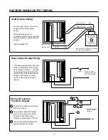
4. Make and break a connection between terminals 4
and 20 using a jumper wire. The main counter and
totalizer should count up each time the connection
makes. If the counters do not count, send the unit to
the factory for repair.
5. Make and break a connection between terminals 4
and 19 using a jumper wire. The main counter and
totalizer should count down each time the connec-
tion makes. If the counters do not count, send the
unit to the factory for repair.
C. If the counter counted from the manual count source in
step B above, reconnect the sensor and select the
correct dip switch setting. For sensors with a DC pulse
output, perform steps 1 and 2. For magnetic pickup
sensors, proceed to step 3 below.
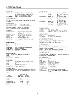
1. With the sensor output in the high state, measure
the voltage between DC Common and the count
input. The voltage must be greater than 3.5 VDC. If
it is lower, the sensor is defective, leaky, or is not
compatible with the counter. With current sinking
sensors, try adding a pull-up resistor (470 ohms to
4700 ohms) from terminal 1 to the count input.
Note: for AC powered counters, the maximum cur-
rent out of terminal 1 must not exceed 100 mA.
2. With the sensor output in the low state, measure the
voltage between DC Common and the count input.
The voltage must be less than 1.9 VDC. If it is
higher, the sensor is defective, leaky, or is not
compatible with the counter. With current sourcing
sensors, try adding a pull-down resistor (220 to
2200 ohms) from the count input to DC Common.
Note: for AC powered counters, the maximum cur-
rent out of terminal 1 must not exceed 100 mA.
3. For magnetic pickup sensors, measure the AC
voltage output of the sensor with the machine
running. The output voltage should be greater than
0.45 volts RMS (1.2 volts peak to peak). If it is less,
the sensor is defective, or the target is too far from
the sensor, or the target is not moving fast enough.
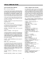
III. Error Message On Display:
The message “ERROR” followed by a single digit number on
the display indicates that the counter’s internal self-tests
have detected a problem. See the self-test section of this
manual (page 24) to determine what caused the problem and
how to solve it.
IV. Other Problems:
Other problems are usually caused by programming and/or
wiring errors. Because of the versatility of this counter, it is
impossible to include troubleshooting instructions for every
situation that could arise. However, the following general
troubleshooting steps should help in resolving specific prob-
lems:
1. Define, in detail, exactly what the problem is and when it
occurs.
2. Use the block diagram and/or the menu programming
diagram to determine which program options or parame-
ters are related to the problem. Check their setting.
3. Determine which I/O circuits are related to the problem
and check their operation with a voltmeter at the counter’s
terminal strips.
If going through the above 3 steps did not lead you to a so-
lution, perform the following:
1. Record the wiring connections to each terminal on the
unit.
2. Place the unit in the run mode and press the help key.
Write down the 4 lines of data. The Ambassador help
screens are provided as an alternate method of determin-
ing a unit's programming. The two help screens contain
32 characters of information. Pressing the HELP/• key
displays screen 1. The characters are arranged as shown
below:
1
2
3
4
5
6
7
8
16
15
14
13
12
11
10
9
Help Screen Character Numbers - Screen 1
Press the down arrow key to display screen 2.
17 18 19 20 21 22 23 24
32
31
30
29
28
27
26
25
Help Screen Character Numbers - Screen 2
3.
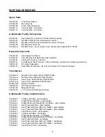
Call the Durant application help line (800-540-9242) and
ask for an application engineer to assist you with trouble
shooting.
TROUBLESHOOTING


