7
3. Operation and Configuration
EAFR-101 Arc Point Sensor Relay User Manual
MN026004EN February 2016 www.eaton.com
3.5.1 Configuration Select Dipswitch Settings
This section describes the available configurations that are
available using the Configuration Select 1 through 4 dip-
switches.
3.5.1.1 Configuration Selection 0
The EAFR-101 logic Configuration 0 can be not only applied
as stand-alone arc protection relay, but also widely used
as non-selective outgoing feeder compartment protection.
Dependent on this configuration, the user can select either
light only mode or arc light + over-current mode to trip all
circuit breakers. The detailed instruction is described in
EAFR Standard Arc Configurations booklet.
Table 3. General Trip Logic for the EAFR-101 Standard
Arc Configuration 0.
Tripping Signals Fault Location T1
T2
T3
T4
BO1
S1
x
x
x
x
x
S2
x
x
x
x
x
S3 and S4
x
x
x
x
x
BI1
x
x
x
x
BI2
x
x
x
x
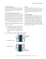
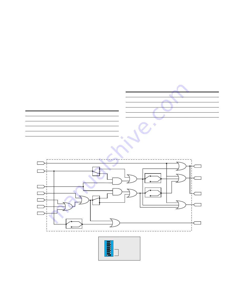
Figure 6. EAFR-101 Configuration Selection 1.
BI1
S1
S2
S3
S4
S5
&
&
OR
OR
OR
OR
OR
T1
T2
T3
T4
BO1
Logic diagram
OFF
ON
SW1/8
OR
ON
OFF
SW1/7
OR
SW1/5
100ms
150ms
ON
OFF
SW1/5
100ms
150ms
ON
OFF
SW1/5
100ms
150ms
ON
OFF
OR
BI2
ON
OFF
Setting EAFR101
SW1
100 / 150 ms
Latch / Non Latch
S1: Light / Light and Current
Light / Light and Current
Configuration Select
8
7
6
5
4
3
2
1
EAFR-101 Configuration 1
3.5.1.2 Configuration Selection 1
The EAFR-101 logic Configuration 1 is mainly utilized in
selective arc protection solutions. The point sensor S1
monitors the outgoing feeder cable compartment. The
point sensor S2 monitors the corresponding feeder breaker
compartment and busbar compartment. Trip contact T1 is
responsible for tripping circuit breaker of the outgoing feed-
er. The detailed instruction is described in EAFR Standard
Arc Configurations booklet.
Table 4. General Trip Logic for the EAFR-101 Standard
Arc Configuration 1.
Tripping Signals Fault Location T1
T2
T3
T4
BO1
S1
x
x
x
S2
x
x
S3 and S4
x
x
BI1
x
x
x
BI2
x
x
x
x


