8
4. Arc Sensors
EAFR-101 Arc Point Sensor Relay User Manual
MN026004EN February 2016 www.eaton.com
3.6 Non-volatile Memory
All critical system data, including dipswitch settings and
auto-configuration file described in Section 3.3.1, are stored
in EPROM non-volatile memory to ensure correct operation
and full self-supervision, even if auxiliary power is temporar-
ily lost.
Also, all LED indications described in Section 3.1 are stored
in non-volatile memory in order to provide quick recovery of
the system status indication, even if auxiliary power is tem-
porarily lost. This feature is especially important if auxiliary
power is lost after tripping.
Non-volatile memory does not require a power supply to
maintain information and will retain settings and indications
permanently without power.
4. Arc Sensors
The EAFR-101 relay series provides the use of point arc light
sensors to be utilized in different switchgear types, accord-
ing to the specific application requirements. Arc light point
sensors are typically installed in metal clad compartments,
providing quick accurate location of the faulted area.
4.1 Arc Light Point Sensor EAFR-01
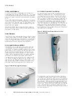
The EAFR-01 is an arc light point sensor with a light sensi-
tive photodiode element activated by receiving arc light.
The EAFR-01 arc sensors should be mounted in the switch-
gear cubicles in such a way that the light sensitive part can
receive light from the protected area. Typically, one sen-
sor per closed metal clad compartment is used. In open
spaces, such as the busbar section, arc sensors should be
mounted at a maximum of two meters (6.56 ft) apart.
The fixed light sensitivity of the EAFR-01-A sensor is 8000
Lux. The sensor does not require any user settings. The
point sensor’s light detection radius is 180 degrees. Other
point sensors are available with different Lux sensitivities,
EAFR-01-B at 25,000 Lux and EAFR-01-C at 50,000 Lux.
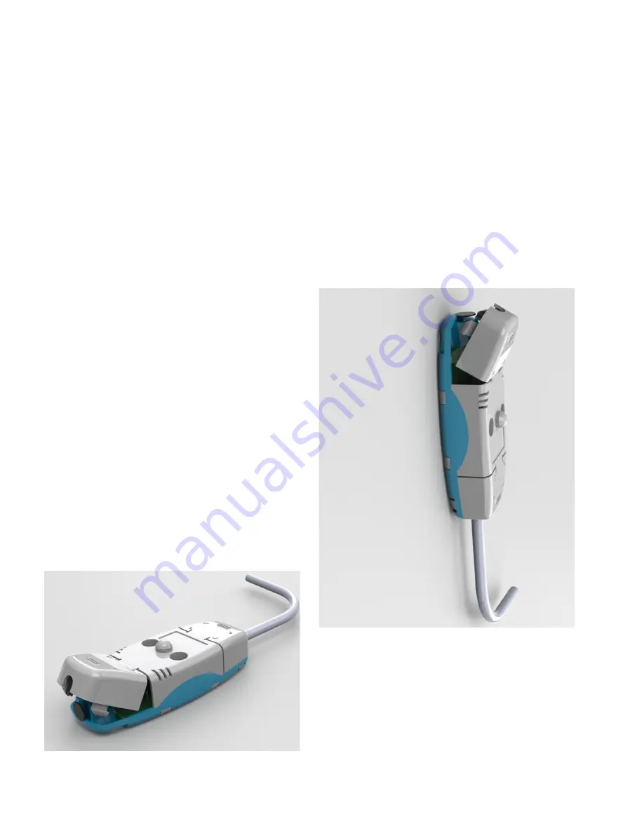
Figure 7. EAFR-01 Arc Light Point Sensor.
4.1.1 EAFR-01 Installation and Wiring
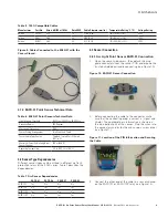
The EAFR-01 point sensor can be installed either on or
through the compartment wall. An example of on the
wall mounting is seen in Figure 8. The EAFR-01 is fixed
against the wall using two screws. The same screw pat-
tern is utilized in a through wall mounting arrangement. In
this arrangement the unit is turned around and the point
of the eye of the photodiode sensor protrudes through a
small hole cut in the wall. The point of the sensor now
faces the compartment to be protected. This allows for the
body of the sensor and cabling to be located outside the
compartment. For both types of installation, two screws
are attached from the back side of the sensor. No external
mounting plates are needed.
Figure 8. EAFR-01 Point Sensor Mounted to the
Compartment Wall.
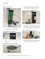
The cable to be used for wiring to the sensor should be
a shielded, twisted pair cable. Table 5 lists several cables
that can be used. Equivalent cable styles are acceptable to
be used for the dielectric and temperature requirements of
the application. Cable connectors are located beneath the
covers that can be conveniently detached for fastening the
sensor wires. The cover will be attached after installing the
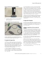
wires. Cable connectors are located at both ends of the
sensor for series connecting a maximum of three sensors in
one line (see Figure 9).


