15
7. Connections
EAFR-101 Arc Point Sensor Relay User Manual
MN026004EN February 2016 www.eaton.com
6.3 Circuit Breaker Failure Protection (CBFP)
The EAFR-101 includes a selective circuit breaker failure
function which can be enabled by dipswitch setting (see
Section 3.5: Dipswitch Settings). When enabled, the break-
er failure function activates when the tripped breaker fails
to operate. The breaker failure function is activated if the
EAFR-101 detects the presence of light after a set operating
time. When EAFR-101 is set to operate on light and current,
both parameters must persist to activate CBFP. Breaker fail-
ure can be set to operate either on 100 ms or 150 ms delay
(Section 3.5: Dipswitch Settings).
7. Connections
7.1 Outputs
7.1.1 Trip Relays T1 and T2
The EAFR-101 relay has integrated trip relays T1 and T2 for
tripping of the circuit breakers. The T1 and T2 relays are nor-
mally open type (NO).
7.1.2 Trip Relays T3 and T4
The T3 relay output may act either as an electronic lock-out
relay or as a trip relay. This option must be specified when
ordering. When the T3 is factory configured as electronic
lock-out relay, it is normally open type (NO) and will hold its
position until manual reset command or until auxiliary power
supply is lost. When re-applying the auxiliary power supply,
the electronic lock-out relay will return to the contact condi-
tion prior to loosing the auxiliary power. This NC relay out-
put can be used for tripping contactor controlled devices.
Alternately, the T3 relay can be ordered as normally closed
(NC) type relay EAFR-101B, EAFR-101DB.
The T3 relay follows the operation of T1 and activates when-
ever T1 is activated.
Trip relay T4 is a common trip relay that operates anytime
the T1 or T2 relay operates and can be used either for trip-
ping one more disconnecting device or for trip alarm to local
or remote monitoring and alarming system.
7.1.3 Binary Output BO1
One binary output is available (+24 Vdc). The binary output
function can be configured using dipswitches (see Section
3.5: Dipswitch Settings).
otee:
N
The binary output is polarity sensitive (see Section 8:
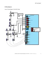
Wiring Diagram).
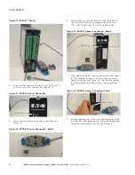
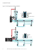
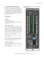
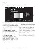
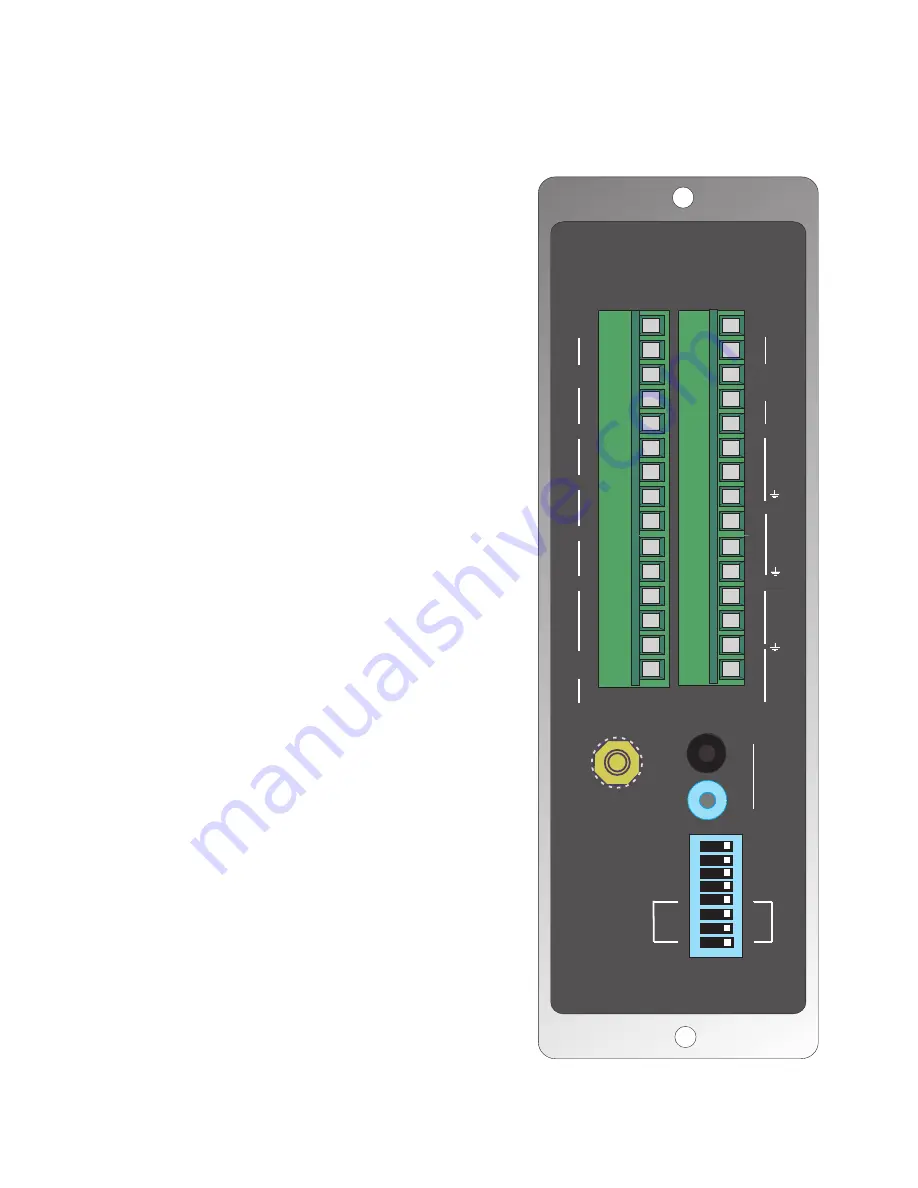
Figure 21. EAFR-101 Terminals at Rear Plate and EAFR-
101D Connections.
15
14
13
12
11
10
9
8
7
6
5
4
3
2
1
X2 X1
RX
TX
S5
GND
15
14
13
12
11
10
9
8
7
6
5
4
3
2
1
1I
B
1
T
2
T
3
T
4
T
F
S
x
ua
U
2I
B
1
O
B
+
1
S
+
2
S
+
3
S
+
4
S
+
+
+
+
EAFR-101
SW1
T1 / T2
L
Config.
Select
L
CBFP Time
150
N L
L+C
L+C
L = Light
100
Latch
S2/S3/S4 Chan
S1 Channel
C = Current
N L = Non Latch

