16
7. Connections
EAFR-101 Arc Point Sensor Relay User Manual
MN026004EN February 2016 www.eaton.com
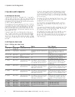
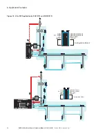
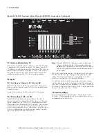
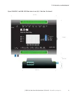
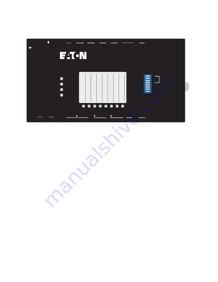
Figure 20. EAFR-101 Terminals at Rear Plate and EAFR-101D Connections. (Continued).
S5 S4 S3 S2 S1 BO1 BI2 BI1
ERROR
T1,T3,T4
T2,T4
POWER
X1
X2
1
2
3
4
5
6
7
8
9
10 11 12 13 14 15
S5
TX RX
15
13
10
9
8
7
6
5
4
3
2
1
S4 + S3 + S2 + S1 + BO1 BI2
+
+
BI1 T1 T2 T3 T4 SF Uaux
+
+
14
12 11
EAFR-101D
Eaton Arc Flash Relay
SW1
SET
EAFR-101D
Pantone Coated
Background = Black
Text = White
LED windows = 427 C (Matte window)
Inside button = Eaton Blue
Pantone 300 C
Logo = White
Adjacent to the LED texts a pocket
is made for inserting custom texts.
66B2286H01
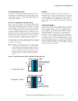
SW1
150
Non Latch
Light + Current
100
Light
Latch
Light
Configuration
Select
8
7
6
5
4
3
2
1
Light + Current
CBFP Time
T1 / T2
S1 Chan
S2/S3/S4
otee:
N
When the EAFR-101 receives an over-current signal
from a non-Eaton device, the actual operation time
depends on the operation time of the external device
and so total operational time cannot be specified or
guaranteed.
BI2 can be used for receiving a trip signal or arc light signal.
The BI2 can be used for receiving a trip signal or arc light
signal. The function of the BI2 is configured using dip-
switches (see Section 3.5: Dipswitch Settings).
The inputs are activated by connecting a dc signal exceed-
ing the specified nominal threshold level of the correspond-
ing input. The nominal threshold level is 24 Vdc. The actual
activation of the binary input occurs at 80% of the specified
nominal threshold value (i.e.: 19 Vdc).
7.3 Auxiliary Voltage
The auxiliary power supply voltage is (110-220) Vac / (125-
250) Vdc. After powering up the relay, protection is active
and operational within 50 ms.
7.1.4 System Failure Relay SF
The system failure (SF) relay is a form C type (NO/NC) and
is energized in the healthy condition. Whenever the EAFR-
101 detects a system error or disconnection of the auxiliary
power supply, the contact changes its state. The state of
the SF relay remains the same until the relay returns to a
healthy condition and the SF relay is again energized.
7.2 Inputs
7.2.1 Arc Sensor Channels S1, S2, and S3
EAFR-101 has four arc point sensor channels. Maximum
three arc point sensors (type EAFR-01) may be connected
to each channel.
For details on sensors, refer to Section 4: Arc Sensors.
7.2.2 Binary Inputs BI1 and BI2
The EAFR-101 contains two binary inputs. The BI1 is
always reserved for second trip criteria signal. In the most
typical application, the EAFR-101 is receiving over-current
information from the Eaton EAFR-110 device. Over-current
information may come also from a non-Eaton device (e.g.:
an upstream protection relay). Alternately, any other signal
(such as under-voltage, or similar) can be used as second
trip criteria along with light information.

