4
645M 4G/LTE CELLULAR ROUTER
MN032003EN March 2017 www.eaton.com
1.6 External connectors
This section describes the external connectors for the
645M router.
•
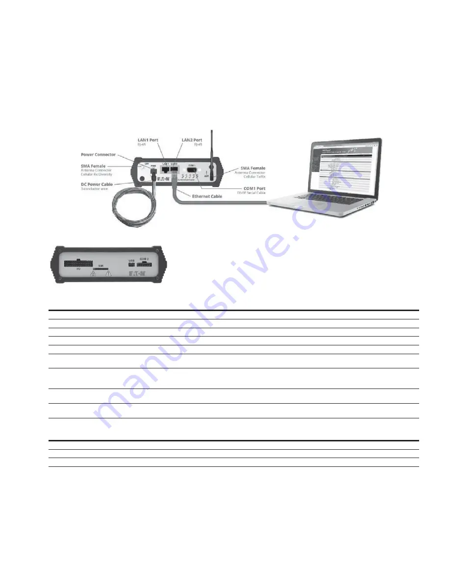
Figure 4 shows the front panel connections
•
Figure 5 shows the rear panel
Figure 4 . Front panel
–
standard fixed models
Figure 5 . Rear panel connections
Table 4 . External connectors
Panel indicators
Connection
Description
COM 1
RS-232 / RS-485
Serial to IP conversion use
ANT
SMA
Primary RF Antenna
DIV
SMA
Cellular Diversity Antenna
LAN 1, LAN 2
RJ-45
Interface for Ethernet connection to devices
USB
USB Mini
Available for diagnostic use.
RESET
Depress switch to reset router. Press and hold during boot to revert settings to
factory defaults.
PWR Jack
Molex 43025-0400 receptacle for four-pin power plug with
optional ignition sense
Bottom pins: +9-32VDC power (pin 1) and ground (pin 2)
Top pins: optional ignition-sense (3) and not connected (4).
See diagram for compatible cable on the following page.
SIM
SIM Card socket
Interface for SIM card (Mini-SIM “2FF” form factor). Your wireless service
provider will supply the SIM card with your wireless service contract.
COM 2
Molex 43650-0501 receptacle for 5-pin RS-232 TTL adapter
5-Pin TTL Serial Port
Available for diagnostic use. Serial port – Level conversion cable required.
Table 5 . Status LEDs
Function
Off
Green
Flash green
Red
Flash red
Amber
Flash amber
RSSI
Strong
Weak/None
Medium
SVC
3G/4G
3G/4G/NC
NC
2G
2G/NC
NET
No connectivity
Rx data
Tx data
Rx/Tx
•
If SVC is solid, then the modem is connected to the cellular
network. If it is flashing, the modem is trying to connect
to the network
The behavior of the LEDs is different than the table at boot. The
boot sequence is: all red, all off, all amber, all green, all flash
green three times, and then the boot sequence is complete.
1 Product overview


