20
User Manual
MN032006EN
Effective December 2017
415U Condor-long-range
wireless I/O and gateway
EATON
www.eaton.com
Networking
Click
Networking
in the project tree to configure Ethernet and
routing parameters. These parameters are described in detail in
this section.
Note
: The default networking mode for the 415U-2 uses bridged
networking. This connects the radio and Ethernet ports to the same
logical sub-net. The 415U-2 device has a single IP address common
to the radio and Ethernet ports.
IP routing
The IP routing rules table determines which IP address an outgoing
message will be routed through. When the table contains enabled
routing rules, the most explicit and exclusive subnet match is used
to determine the route for an outgoing message. If there is no
match, the 415U-2 checks for a subnet match against its hard-wired
Ethernet interface. If that does not match, it attempts to use the
default gateway (configured on the main device configuration page),
assuming that the default gateway is configured and accessible.
In some cases, such as routed networks with more than two
routers, it is not practical to have only one default gateway. If more
than one next-hop router is required, the 415U-2 allows for the
configuration of up to 100 routing rules. A routing rule specifies
a destination network (or host) IP address and the corresponding
next-hop router (gateway) to which messages for the specified
destination will be forwarded. The gateway will then deliver the
data to the required destination, or forward it on to another router
that will.
Note
: IP routing is an advanced user function. If you are not
familiar with IP routing and your network consists of multiple
sub-networks connected by routers, request assistance from an
IT expert.
To display the IP routing rules table, click
Routing
under
Networking
. After configuring routing rules, click the
Program Unit
button on the module’s Unit Details screen for the changes to
take effect.
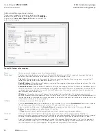
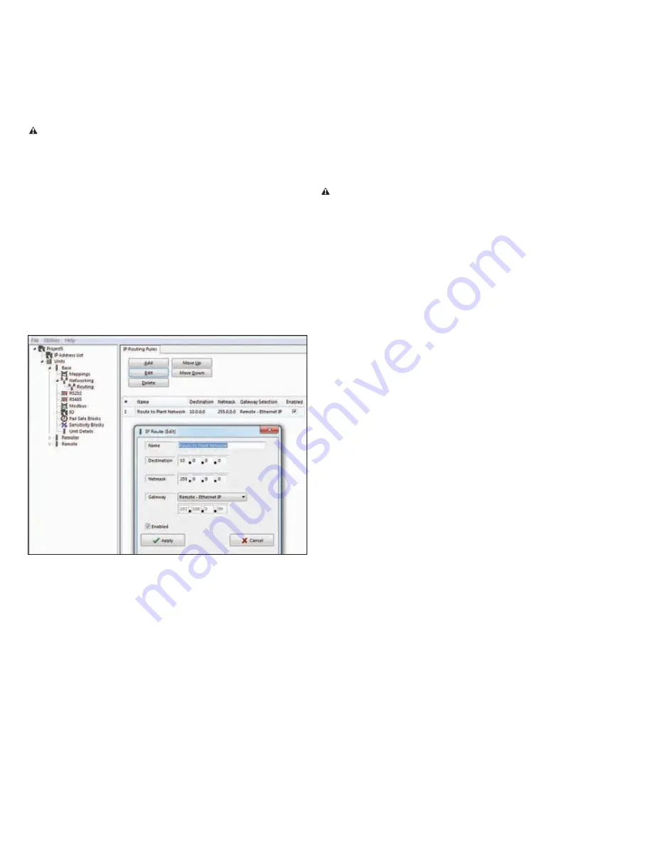
The example in
Figure 33
shows an IP routing rule that maps
messages to any IP address starting with 10.0.0.0 to the gateway
with the IP address 192.168.0.254.
Figure 33. IP routing rules
Add
Adds a new IP routing rule. A new blank entry is added to the table. Enter the information for the new rule, and click
Save
changes
.
Edit
Allows you to edit information for a selected IP routing rule.
Delete
Remove a selected IP routing rule.
Move up
Move down
Moves a selected IP routing rule within the list.
Name
Name describing the routing rule (maximum 32 characters).
Destination
Destination network or host IP address. You can specify an entire network by entering the IP range 192.168.0.0 with a
netmask of 255.255.255.0, or you can specify an individual host IP address by setting the netmask to 255.255.255.255.
Netmask
Subnet mask for the destination network.
Interface
The interface to use for the route. You can choose Radio, Ethernet, or Any.
Gateway
Specifies the IP address of the next-hop router for the specified destination.
Enabled
Select this checkbox to enable the routing rule. Clear this checkbox to disable the routing rule without deleting it.
Mappings
Mappings are used to send I/O values between modules using
the WIB I/O transfer protocol. The I/O is sent to a remote module


