71
User Manual
MN032006EN
Effective December 2017
415U Condor-long-range
wireless I/O and gateway
EATON
www.eaton.com
Register memory map
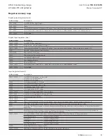
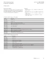
Digital output registers (coils)
Address range
Description
0001 – 0008
Local DIO1–DIO8 as digital outputs
0009 – 0020
Spare
0021 – 0400
Space for locally attached 115s expansion I/O modules. Twenty register per module address, maximum number of modules is 19.
0401 – 6000
General purpose bit storage used for: Staging area for data concentrator; Fieldbus mappings storage; Force mapping registers
6001 – 10000
Not Available
Digital input registers (bits)
Address range
Description
10001 – 10008
Local DIO1–DIO8 as digital inputs
10009 – 10020
Set point status from analog inputs 1 through 12
10021 – 10400
Space for locally attached 115s expansion I/O modules. Twenty register per module address, Maximum number of modules is 19.
10401
Reserved - Used for repeater status indication
10402-10405
Radio hard fault status flags
10402
Radio power amplifier over temperature
10403
Radio general hardware fault
10404
Radio frequency lock error
10405
Antenna VSWR fault
10406 – 16000
General purpose bit storage used for: Staging area for data concentrator; Fieldbus mappings storage;
16001 – 20000
Not Available
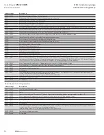
Input registers (words)
Address range
Description
30001 – 30004
Local AI1–AI4 (analog inputs, current mode)
AI1 and AI2: 4–20 mA differential
AI3 and AI4: 4–20 mA sink
30005
Local supply voltage (0–40 V scaling)
30006
Local 24 V loop voltage (0–40 V scaling)
30007
Local battery voltage (0–40 V scaling)
30008
115S supply voltage (0–40 V scaling)
30009 – 30010
Local AI1, AI2, Voltage Mode. 0-24V Scales to 0-24mA.
30011 – 30012
Local AI3, AI4, Voltage Mode. 0-5V Scales to 0-20mA
30013 – 30016
Local pulse input rates: PI1–PI4
30018 – 30020
Spare
30021 - 30400
Space for locally attached 115s expansion I/O modules. Twenty registers per module address, maximum number of modules is 19.
30401
RSSI: When configured as a Remote, Repeater, or Manual Client, the RSSI of the connected upstream device in –dBm
30402
Connected Time: When configured as a Remote, Repeater, or Manual Client, the time (in hours) that the connection to the upstream device has
been made.
30403
Generation Count: When configured as a Remote, Repeater, or Manual Client, the generation count of the connection to the upstream device.
This is the number of times the connection has been lost and re-established
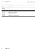
30404 – 30405
Upstream IP Address: When configured as a Remote, Repeater, or Manual Client, the IP Address of the upstream device.
Most Significant Byte
High byte of Register 30404
Second Byte
Low byte of Register 30404
Third Byte
High byte of register 30405
Least Significant Byte
Low byte of register 30405
30406
Current Radio Channel for frequency agility
30407 – 30408
Radio Transmit Frequency (in Hz). 32-bit. Most significant word at lower (odd) address.

