7
Instruction Leaflet
IL29C204I
Effective Octoberr 2011
Installation Instructions for Motor Operator for
3- and 4-Pole ND, NB, NC, MD, MA, MC Type
Circuit Breakers and Molded Case Switches
EATON CORPORATION
www.eaton.com
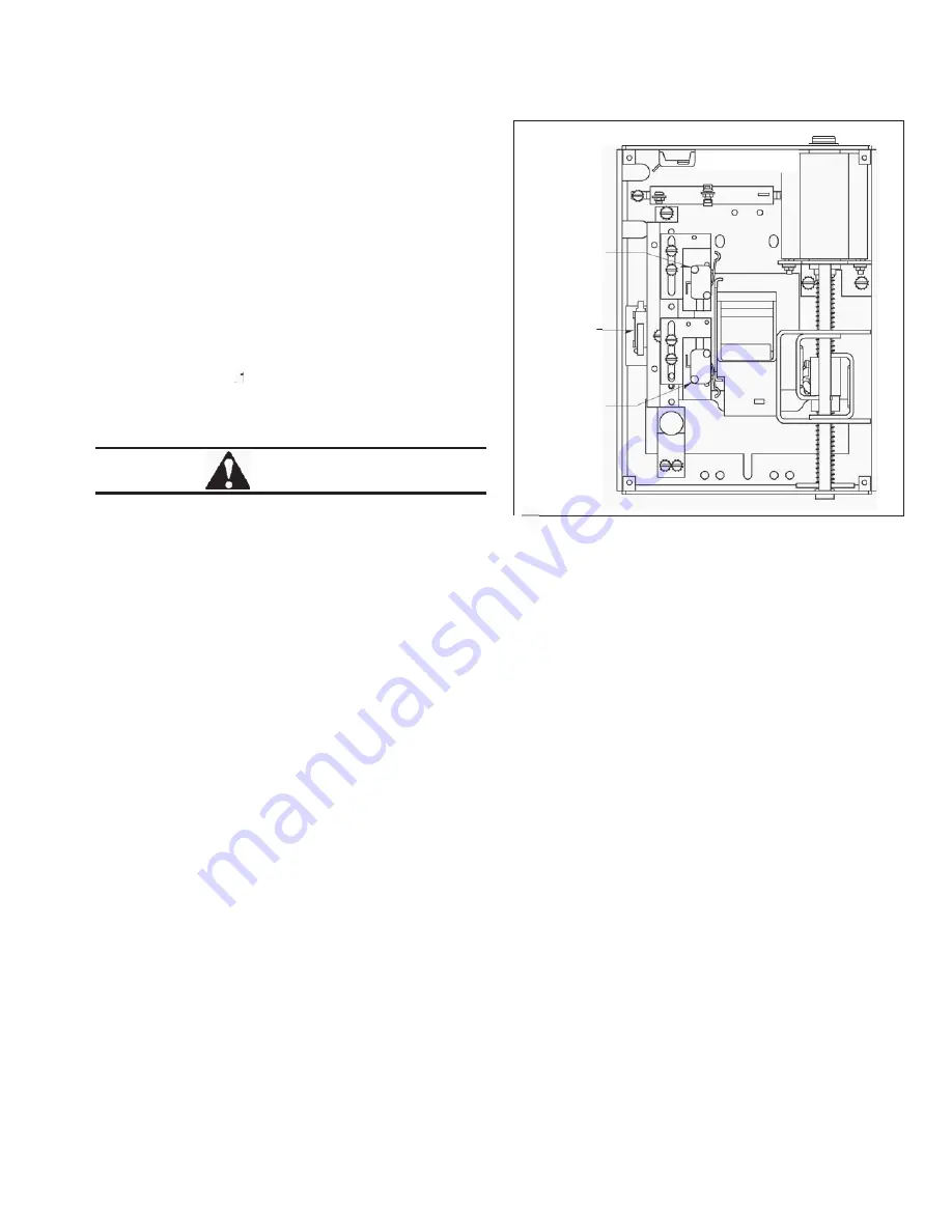
Two limit switches control the travel of the motor operator
carriage. The upper switch de-energizes the motor when
the carriage has moved sufficiently to close the circuit
breaker. The lower switch de-energizes the motor when
the carriage has moved sufficiently to reset the circuit
breaker.
4-1. Disconnect the motor operator from the supply volt-
age.
4-2. Remove the cover screws and the motor operator
cover.
4-3. Use a .125-in. dia. pin (customer supplied) and
insert into the 30-in. dia. hole near the “POWER-
OFF” switch to hold switch
“ON”
(Figs. 3-1 and 4-1).
CAUTION
.125 IN. DIA. PIN SHOULD BE REMOVED BEFORE
REINSTALLING THE COVER.
4-4. For upper limit switch adjustment, loosen the two
pan head screws securing the upper switch assem-
bly. Move the switch up to increase the carriage
travel. Move the switch down to decrease the car-
riage travel. After adjusting, tighten the screws.
Upper Limit
Switch
Power-Off
Switch
Lower Limit
Switch
r
Fig. 4-1.
Motor Operator Limit Switch Locations
4-5. For lower limit switch adjustment, loosen the two
pan head screws securing the lower switch assem-
bly. Move the switch down to increase the carriage
travel. Move the switch up to decrease the carriage
travel. After adjusting, tighten the screws.
4-6. Replace the motor operator cover and cover
screws.
4-7. Reconnect the motor operator to the supply volt-
age, reset.


