background image

Eaton ePDU G3 Troubleshooting Guide    P-164000278—Rev 1    

www.eaton.com/ePDU

10

Chapter 3

Troubleshooting

This chapter provides details for troubleshooting power outlets for the Eaton Enclosure Power Distribution Unit 
(ePDU) G3 models. The following tables list fault conditions, potential causes, and possible troubleshooting 
actions you can take in response to problems.

!

IMPORTANT

Be aware that unplugging the ePDU from the power source will turn off power to all connected 
loads and equipment.

Power Outlets

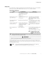
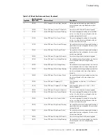
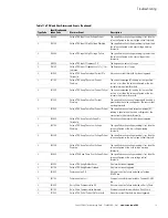
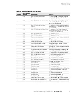
Table 5. Power Outlet Troubleshooting  

Problem

Possible Root Cause

Actions

Outlet LED is Off: No power to 
the outlet, but the Web 
interface reports that the 
outlet is On

l


Web interface is locked

l


Communication issue

l


Internal issue

l


Wrong IP address: You are 

monitoring the wrong ePDU

1 - Press the F5 or page refresh button in the Web browser.

2 - Close and restart the Web browser or try another Web browser, 
such as Google Chrome, Firefox, or Opera.

3 - Refer to the 

Eaton ePDU G3 Operations Manual

 and/or restart the 

ePDU Network Management and Control module with the reset button 
(R) on the product (press for 1


or 2


seconds). Outlets will not restart 

during this process.

4 - Cycle the outlet control (On/Off) using the Web interface. If the 
outlet LED is still Off, restart the ePDU and then reconnect the device to 
the ePDU.

5 - Check the Media Access Control (MAC) address on the device and 
check the MAC address in the Web interface.

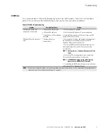
Outlet LED is On, but there is 
no power to outlet

l


Circuit breaker (CB) has 

tripped

l


Internal issue (outlet relay is 

open)

1 - Check the CB state on the ePDU.

NOTE

For Managed (MA), Switched (SW), and (optionally) 
Metered Input (MI) ePDUs, the LED normally flashes 
RED when a CB is tripped. If the LED is alternately 
flashing green and red, the outlet is On, but there is a 
breaker overload.

2 - Restart the ePDU and check again.

Outlet LED is Off, but there is 
power to outlet

l


Internal failure

1 - Cycle the outlet (On/Off) using the Web interface.

2 - Restart the product and check again.

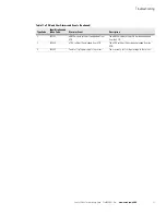
Outlet LED is blinking

l


Critical alarm on the outlet

l


Internal failure

1 - Check the LCD screen. If the LCD screen is flashing red, a critical 
alarm is present. Check the outlet settings, measurements, and 
electrical conditions. The alarm does not clear until the outlet condition 
is back to normal (cannot manually suppress the alarm).

IEC plug falls from the ePDU 
during normal operation

l


The cord was not fully seated 

before the lever grip switch 
was set to close

l


The lever grip switch is set to 

open rather than close

1 - Reseat the plug in the outlet, then ensure that the lever grip switch 
is pointing to the + sign.

NOTE

If the actions listed in this table do not resolve the problem, contact customer service or a local representative for guidance and/or 
replacement (see “Contacting Service and Support” on page 5).

Summary of Contents for EPBZ99

Page 1: ...Eaton Enclosure Power Distribution Unit ePDU G3 Troubleshooting Guide...

Page 2: ...emarks of Microsoft Corporation in the United States and other countries Mozilla and Firefox are registered trademarks of the Mozilla Foundation National Electrical Code and NEC are registered tradema...

Page 3: ...munications Operation of this equipment in a residential area is likely to cause harmful interference in which case the user will be required to correct the interference at his own expense ICES 003 Th...

Page 4: ...risk of electric shock symbol CAUTION REFER TO OPERATOR S MANUAL Refer to your operator s manual for additional information such as important operating and maintenance instructions This symbol indica...

Page 5: ...5 Resolving Problems 6 Clearing Alarm Notifications 6 Clear the Web Interface Event Log 6 Suppress ePDU Alarm Indicators 6 Contacting Service and Support 7 2 SAFETY WARNINGS 8 3 TROUBLESHOOTING 10 Po...

Page 6: ...response l Error Messages Error messages display due to incorrect entries or failed processes An error message prompts you to provide correct information or retry an operation Identifying Problems The...

Page 7: ...alarm screen Scroll up or down if needed to view active alarm data When you finish your review press ESC to return to the previous menu If the backlight was blinking red to indicate an active alarm th...

Page 8: ...t no activity FLASHING Port is sending or receiving transmission active 7 Reset Button NOTETo restart the eNMC module insert a probe and press the button This does not reset power to the outlets 8 USB...

Page 9: ...larm information for the ePDU model you are using see Figure 4 3 4 2 1 5 Figure 4 ePDU Web Interface Opening Window NOTE The data that displays on the Web interface depends on the type of ePDU model y...

Page 10: ...are active alarms such as Warning some alarms fired please refer to the Active Alarms Last Refresh dd mm yyyy hh hh ss An alarm indicator also appears as a notification in the refresh bar at the botto...

Page 11: ...that may help you solve problems The alarms and events table provides the alarm event identification code and name a description of the alarm event and suggested troubleshooting actions If you cannot...

Page 12: ...rvice l Model number l Serial number l Date of failure or problem l Symptoms of failure or problem l Customer return address and contact information Table 4 provides the Eaton catalog part number for...

Page 13: ...ture must be within the operating range of the selected model l Do not use a two wire power cord in any product configuration l Test AC outlets at your computer and monitor for proper polarity and gro...

Page 14: ...rnal ePDU Network Management and Control eNMC module l The battery is not user replaceable There is risk of explosion if battery is replaced by an incorrect type l Ensure that used batteries are dispo...

Page 15: ...evice to the ePDU 5 Check the Media Access Control MAC address on the device and check the MAC address in the Web interface Outlet LED is On but there is no power to outlet l Circuit breaker CB has tr...

Page 16: ...king sound Direct keyhole mounting stripping the hole while threading the hole with the mounting screw l Screwing torque is to high or too fast and has damaged the thread screw should not suffer damag...

Page 17: ...on the LCD even though condition exists l Settings are not kept in ePDU memory after a power cycle On Off if the value is outside of the current or voltage thresholds range l LCD internal failure 1 Ch...

Page 18: ...COM port LEDs are On but do not flash l Communication issue l Internal failure 1 Make sure that IP settings and communication parameters PC and ePDU are set according to the Eaton ePDU G3 Operations M...

Page 19: ...ting actions Identifying the Alarm or Event Condition on the Web Interface You can derive defining information about the alarm or event from the associated number code Figure 5 shows the location of t...

Page 20: ...e Code 1 System Figure 7 Example Type 1 System Code Table 10 lists System alarms and events Table 10 OS or System Alarms and Events Type Code Identification Code Alarm or Event 1 03073 Code unreachabl...

Page 21: ...t used 1 02563 Not used 1 02564 Wrong data type 1 02565 String too long 1 02566 Not used 1 02567 Not used 1 01025 Not used 1 01026 Semantic error 1 01027 Impossible to open log file 1 01028 Impossible...

Page 22: ...e Communication Failure Sensor probe communication failure detected 2 208000 Sensor Probe Not Connected Sensor probe not connected since firmware startup 2 208100 Sensor Probe Connected Sensor probe c...

Page 23: ...t 1 Over Voltage Warning The specified section voltage reading is greater than the value configured as the over voltage warning threshold 2 212400 Eaton ePDU Input 1 Over Voltage Critical The specifie...

Page 24: ...PDU Gang Phase Over Current Critical The specified section input current amperage A reading is greater than the value configured as the over current critical alarm threshold 2 222000 Eaton ePDU Gang P...

Page 25: ...quested by interface An Ethernet card restart has been requested through the specified user interface 3 300600 Switch to bootloader mode for upgrade by interface A Switch to bootloader mode for upgrad...

Page 26: ...settings file has been uploaded from the USB 3 302400 ePDU settings file uploaded from USB The ePDU settings file has been uploaded from the USB 3 302500 Send test syslog message to the server The use...

Page 27: ...m sizes are l 13 125 Kbytes for the eNMC module configuration file l 20 Kbytes for the ePDU configuration file Failed to send a request to the eNMC module Retry later Configuration request failed 1 Tr...

Page 28: ...n the Web interface NOTE Pushing the reset button will not power off the loads NOTE If the actions listed in this table do not resolve the problem contact customer service or a local representative fo...

Page 29: ...nd user supplies a credit card number or purchase order for the value of the replacement Product Company will use commercially reasonable business efforts to ship via standard ground shipment and at n...

Page 30: ...TITUTE COMPANY S SOLE LIABILITY AND ENDUSER S EXCLUSIVE REMEDY FOR FAILURE OF COMPANY TO MEET ITS WARRANTY OBLIGATIONS WHETHER CLAIMS OF THE END USER ARE BASED IN CONTRACT IN TORT INCLUDING NEGLIGENCE...

Page 31: ...eplacement equipment installation materials freight charges travel expenses or labor of Company representatives outside the terms of this Warranty will be borne by the End user OBTAINING WARRANTY SERV...

Reviews: