


Troubleshooting
Eaton ePDU G3 Troubleshooting Guide P-164000278—Rev 1
www.eaton.com/ePDU
11
Chassis and Installation
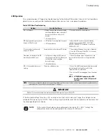
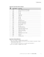
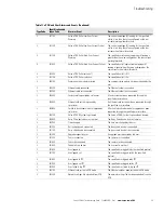
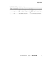
This section provides chassis and hardware installation troubleshooting for the Eaton ePDU models. Table 6
lists fault conditions, potential causes, and possible troubleshooting actions you can take in response to
problems.
Table 6. Chassis and Hardware Installation Troubleshooting
Problem
Possible Root Cause
Actions
Keyhole button: Does not fit
intended rack (cannot insert or
support product)
l
The rack used is different and the wall
thickness does not match the keyhole
design
l
Keyhole part is defective
1 - Unscrew the keyhole button and turn it to the other
side (2.1 mm on one side and 2.2 mm on the other).
Reattach the keyhole button.
Indirect mounting using clip feet
(with keyhole button system):
Difficulty aligning the keyhole
buttons with the rack keyholes
l
Clip feet and keyhole buttons were
incorrectly pre-assembled on the ePDU
before rack installation
1 - First, try to assemble the clip feet and keyhole
buttons. Then, place the two subassemblies in the rack
keyholes. Finally, clip the ePDU inside the installed clip
feet. (You should hear a clicking sound.)
Direct keyhole mounting: stripping
the hole while threading the hole
with the mounting screw
l
Screwing torque is to high or too fast
and has damaged the thread (screw
should not suffer damage)
1 - Try a different hole (shifting the ePDU) or use the clip
foot assembly
NOTE
CAUTION. There is a safety risk if you do
not use the screws that are supplied. Do
not use a substitute.
NOTE
If the actions listed in this table do not resolve the problem, contact customer service or a local representative for guidance and/or
replacement (see “Contacting Service and Support” on page 7).
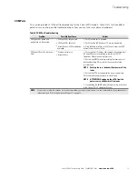
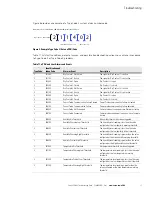
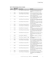
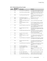
Circuit Breakers
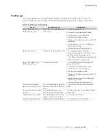
This section provides circuit breaker (CB) troubleshooting for the Eaton ePDU models. Table 7 lists fault
conditions, potential causes, and possible troubleshooting actions you can take in response to problems.
Table 7. Circuit Breaker Troubleshooting
Problem
Possible Root Cause
Actions
CB makes vibration noise during
current overloading state before
tripping
l
Due to the impact of the
electromagnetic field on the CB
internal parts
1 - This is normal behavior if overload is present.
Reduce the current load on the breaker. This action
should reduce or eliminate the noise.
NOTE
If noise persists at or under nominal current, power off your ePDU and contact customer service or a local representative for
guidance and/or replacement (see “Contacting Service and Support” on page 7).


