


IF 267 • 04/20 Copyright © 2020, Eaton’s Crouse-Hinds Division Page 3
If all conductors are alike except one, that one may be assumed to be white
and all the others will probably be in the same relative location from the
white wire at the other end of the same cable. However, lacking positive
color identification of each conductor,
ALWAYS
test them out electrically.
Assuming conductor color identification as described earlier, connect
conductors identified by color in the proper column in Table II through
corresponding contacts in the plug and receptacle identified by number (or
color) listed. The white wire should always be connected through the #2
contact (or white color code). connections.
*White wire or terminal must not be used for grounding. If one conductor is uninsulated, or identified green, this wire is for grounding the portable device. If no green or bare wire is available, another wire
may be connected through plug and receptacle connections to conduit or some other non-current carrying conductor permanently grounded in accordance with Article 250 of the National Electrical Code.
**Use pressure type termination.
***Arktite plugs manufactured prior to 1982.
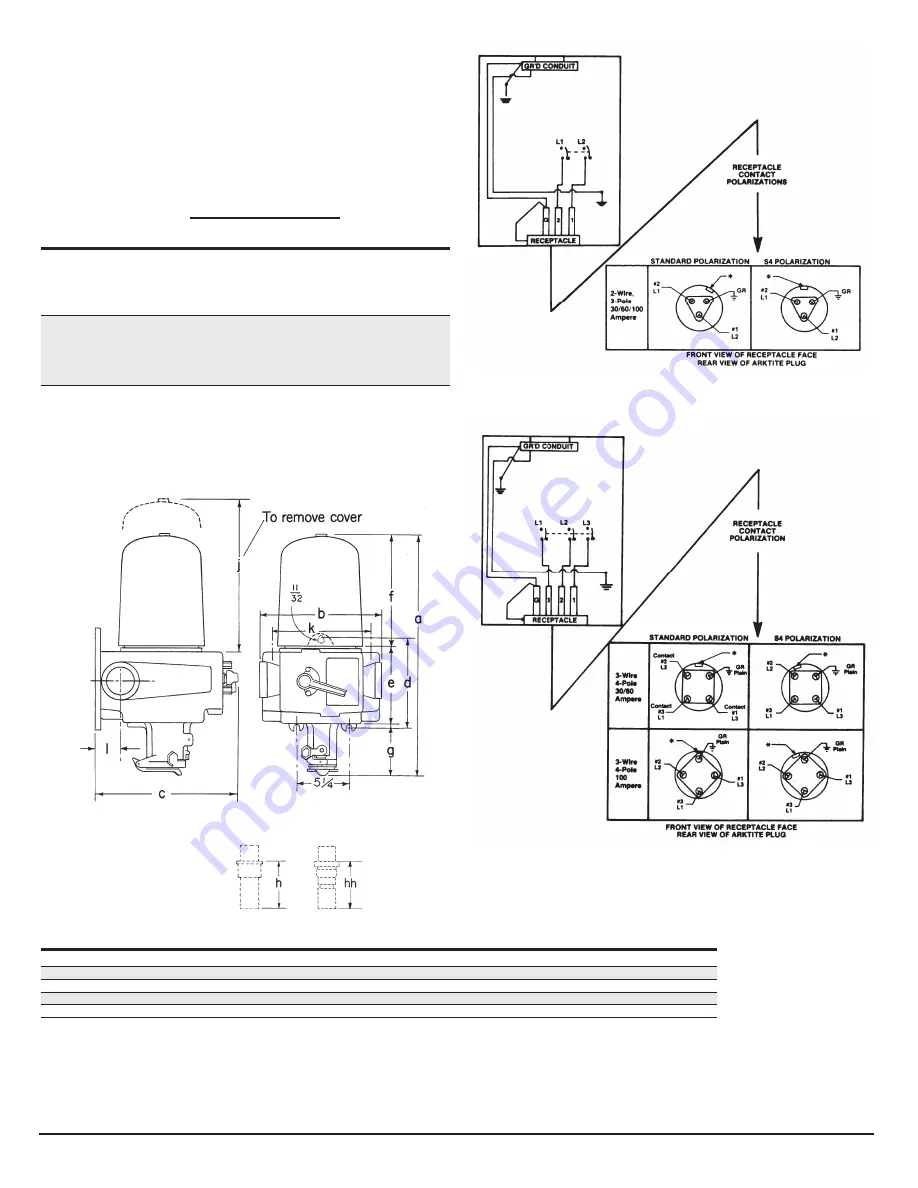
NOTE: EPC enclosures identified with the addition of Suffix S4 to catalog number are supplied with receptacle contacts rotated 22-1 /2 degrees for special polarity applications. They are compatible only with
plugs built with the same special feature.
APJ
NPJ
Dimensions ‘h’ and ‘hh’ are exposed portion of plug when engaged with receptacle.
Receptacle
Breaker
a
b
c
d
e
f
g
h
hh
k
l
30A
20-50A
24
10
5
/
8
14
3
/
8
9
3
/
8
7
11
/
16
11
3
/
4
4
9
/
16
4
13
/
16
7
7
3
/
8
2
1
/
16
60A
50A
24
1
/
2
10
5
/
8
14
3
/
8
9
3
/
8
7
11
/
16
11
3
/
4
5
1
/
16
5
13
/
16
6
13
/
16
7
3
/
8
2
1
/
16
60A
70-100A
24
1
/
2
12
13
/
16
14
3
/
8
9
3
/
8
7
11
/
16
11
3
/
4
5
1
/
16
5
13
/
16
6
13
/
16
9
1
/
4
2
5
/
8
100A
70-100A
25
1
/
4
12
13
/
16
14
3
/
8
9
3
/
8
7
11
/
16
11
3
/
4
5
13
/
16
6
5
/
8
7
3
/
4
9
1
/
4
2
5
/
8
200A
125-225A
36
18
27
13
1
/
2
Receptacle and plug
contact identification
Receptacle
style
Color of
conductors
By number
By
color***
Circuit breaker
line connections
2-wire, 3-pole
White*
Black
Green**
Contact #2
Contact #1
GR (grounding
contact)
White
Red
Unidentified
L1
L2
Ground
3-wire, 4-pole
White*
Black
Red
Green**
Contact #2
Contact #3
Contact #1
GR (grounding
contact)
White
Orange
Red
Unidentified
L2
L1
L3
Ground
Table 2
DIMENSIONS
Figure 1. 2-wire, 3-pole, style 2 contact identification
Figure 2. 3-wire, 4-pole, style 2 contact identification
*Polarization keyway or key
(Keyway is groove, key may be
extended form or rivet)
*Polarization keyway or key
(Keyway is groove, key may be
extended form or rivet)


