3
2
EPM12V2 Evaluation kit user guide
EPM12V2 Evaluation kit user guide
EPM12V2 EVALUATION KIT USER GUIDE
Technical note ELX1037 April 2021 www.eaton.com/magnetics
EPM12V2 EVALUATION KIT USER GUIDE
Technical note ELX1037 April 2021 www.eaton.com/magnetics
Contents
INTRODUCTION
. . . . . . . . . . . . . . . . . . . . . . . . . . . . . . . . . . . . . . . . . . . . . . . . . . . . . . . . .
3
IMPORTANT NOTICE
. . . . . . . . . . . . . . . . . . . . . . . . . . . . . . . . . . . . . . . . . . . . . . . . . . . . . .
3
DESCRIPTION
. . . . . . . . . . . . . . . . . . . . . . . . . . . . . . . . . . . . . . . . . . . . . . . . . . . . . . . . . . . .
3
SPECIFICATION
. . . . . . . . . . . . . . . . . . . . . . . . . . . . . . . . . . . . . . . . . . . . . . . . . . . . . . . . . .
4
TEST SET-UP
. . . . . . . . . . . . . . . . . . . . . . . . . . . . . . . . . . . . . . . . . . . . . . . . . . . . . . . . . .
4-5
OPERATION NOTES
. . . . . . . . . . . . . . . . . . . . . . . . . . . . . . . . . . . . . . . . . . . . . . . . . . . . .
5-9
TEST RESULTS
. . . . . . . . . . . . . . . . . . . . . . . . . . . . . . . . . . . . . . . . . . . . . . . . . . . . . . . . .
10
SCHEMATIC
. . . . . . . . . . . . . . . . . . . . . . . . . . . . . . . . . . . . . . . . . . . . . . . . . . . . . . . . . . . .
11
LAYOUT
. . . . . . . . . . . . . . . . . . . . . . . . . . . . . . . . . . . . . . . . . . . . . . . . . . . . . . . . . . . . . . . .
11
COMPONENT LIST
. . . . . . . . . . . . . . . . . . . . . . . . . . . . . . . . . . . . . . . . . . . . . . . . . . . . . .
11
Introduction
This document describes the operations of evaluation kits (EVK) concerning the Eaton’s EPM DC-DC non-isolated converter
product . The EVK includes test points for all main points where probing is necessary for evaluation . The EVK supports many options
for Eaton’s product configuration . Using these options, the user is allowed to test all desired electrical specifications . This guide
describes the test configurations and typical equipment setup . The typical input and output waveforms are also presented .
Important notice
•
Please read the product datasheet and EVK user guide before using the EVK .
•
Please do not remove the product from the EVK .
•
This product is an ESD sensitive component and should be tested in an ESD protected area .
•
The EVK is designed to operate in clean and dust-free office or laboratory . The EVK should be protected from sunlight and
sources of heat, and making sure air is flowing across the tool . Please keep it away from vibration or strong electromagnetic
fields generated by electrical equipment .
•
When connecting and disconnecting the power interface, please turn off the power supply to avoid accidental short circuits
causing injury .
•
The power connection must avoid reverse voltage application .
•
During the test, the electrical rating should be kept within the range specified in the data sheet .
Description
This EVK supports user test electrical performance of Eaton’s DC-DC non-isolated converter part number EPM12V2-05R5-12R0P
and EPM12V2-05R5-12R0N .
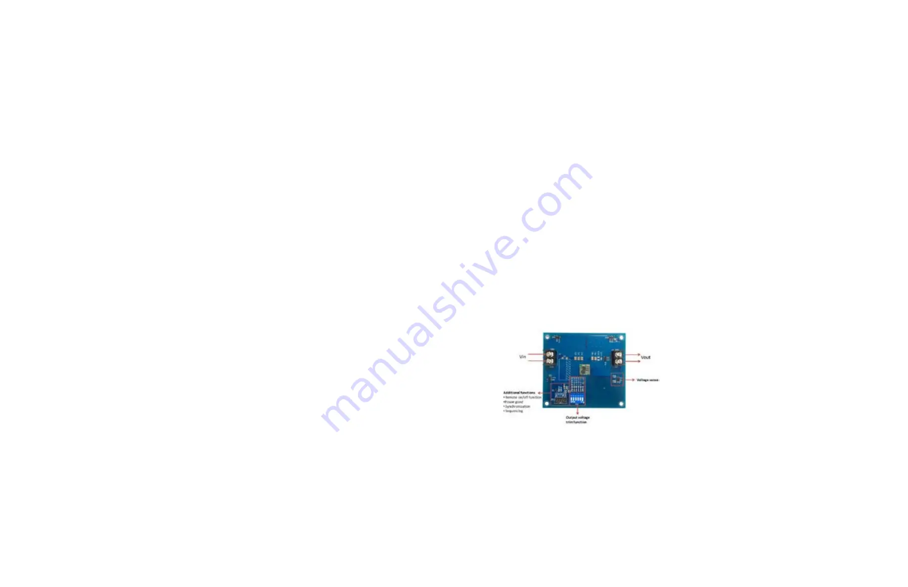
Figure 1 shows the EPM12V2 EVK (PN: EPM12V2-P-EVK, positive logic), (PN:EPM12V2-N-EVK, negative logic) and function outline .
This EVK is made up of the input and output connectors and the DC/DC converter . There are six additional functions, output voltage
trim function, voltage sense, remote on/off function, power good, synchronization, and sequencing .
Figure 1.
EPM12V2 EVK


