13
Operation
OperatiOnal manual
MN156001EN October 2015 www.eaton.com
Voltages
NOTICE
HAZARD OF UNINTENDED EQUIPMENT OPERATION
Enter the External Transformer data according to the
transformer specification.
Failure to follow these instructions may result in
damage to the active filter or other equipment on same
electrical system .
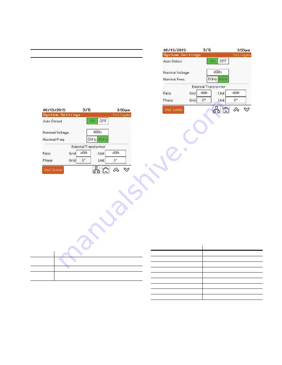
Auto Detecte:
Instructs the controller to determine nominal
grid voltage and frequency when power is applied.
Nominal Voltagee:
With Auto Detect ON, the nominal
voltage is automatically entered. With Auto Detect OFF the
nominal voltage level applied at the input power connection
must be entered. Nominal voltages at 480 V, 415 V, 400 V,
and 380 V are automatically detected. For other nominal
operating voltages, enter them manually.
Nominal Freq .e:
With Auto Detect ON, the nominal
frequency is automatically entered. With Auto Detect
OFF, the nominal frequency applied at the input power
connection must be selected.
Ratio Grid
Enter the voltage rating of the transformer on the grid side.
(Ratio) Unit
Enter the voltage rating of the transformer on the active
filter side.
Phase Grid
The is set to zero. It is not an adjustable parameter.
(Phase) Unit
Touching this data box displays the available phase shift
options for the transformer.
The
External Transformer
section must be changed if there
is an external transformer between the Harmonic Correction
Unit and the voltage bus being corrected. This parameter is
not used for the integrated transformer units. These units
are identified by a rating of 600 or 690 V on the nameplate.
Active filters that are connected to the electrical distribution
systems at voltage levels above the unit’s nameplate
voltage rating require a transformer to step up the voltage
to the desired level. Auto-transformers, Delta-Delta, and
Wye-Wye transformers have no phase shift. Therefore the
AF = parameter is set to 0 degrees. If transformers are
used with a Delta to Wye configuration, the phase shift
must be entered. Typically transformer manufacturers
indicate this in clock face notation. The Grid side of the
transformer is used as the reference and is set to zero
or 12 o’clock. The high voltage side is indicated with a
capital letter. “D” indicates the delta winding is on the high
voltage side. A lower case letter indicates the winding type
of the low voltage side; “y” indicates a wye wound low
voltage side.
Refer to the following table for setting the AF = parameter
based on common transformer nameplate information.
Table 1 . External Transformer AF = Settings
transformer nameplate
unit options aF =
Dy1
30 Lag
Dy2
60 Lag
Dy4
120 Lag
Dy5
150 Lag
Dy6
180
Dy7
150 Lead
Dy8
120 Lead
Dy10
60 Lead
Dy11
30 Lead


