EXTERNAL BYPASS SWITCH INSTALLATION
Eaton FERRUPS FE/QFE UPS (500 VA–18 kVA) Installation Guide
S
164201403 Rev B
www.eaton.com/powerquality
35
NOTE 6
For maximum protection against electrical noise, use isolated
ground receptacles. Refer to NEC Section 250-146(d) or local requirements.
NOTE 7
For service, the UPS requires 36
I
(91.5 cm) clearance on the sides
and in front, 12
I
(30.5 cm) above the UPS, and 4
I
(10.0 cm) behind the UPS.
A minimum clearance of 4
I
(10 cm) is required on the sides, front, and back
and 12
I
(30.5 cm) above the UPS for proper ventilation. See “Equipment
Clearances” on page 20 for clearances before installing the UPS. Use
flexible metal conduit on the UPS or the external battery cabinet if either
must be moved.
NOTE 8
External UPS batteries are optional. The battery cable must not
be disconnected if a load is applied. Shut off the UPS before disconnecting
the cable. See “External Battery Cabinet Installation” on page 55 for
external battery cabinet installation.
NOTE 9
UPS output circuits must be installed in dedicated conduit and
not shared with other electrical circuits.
NOTE 10
The load fuse or circuit breaker should be sized to match the
load current requirements.
NOTE 11
For 208 Vac, use a step-up transformer. For 480 Vac, use a
step-down transformer. Use an isolation transformer with a 120/240
grounded center-tapped neutral output. Do not use a buck/boost
transformer.
NOTE 12
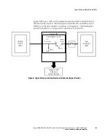
For 120/208/240 models, connect X1 on the UPS to L1 on the
bypass switch; for 208 Vac, connect the bypass switch L2 to the UPS XT1;
for 240 Vac, connect the bypass switch L2 to the UPS XT2.


