background image

Service Manual

Fuller Mid Range Transmissions

TRSM0140

October 2007

Summary of Contents for FS-6105

Page 1: ...Service Manual Fuller Mid Range Transmissions TRSM0140 October 2007 ...

Page 2: ......

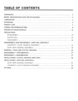
Page 3: ...LY 12 INSPECTION 12 REASSEMBLY 14 DISASSEMBLY AND REASSEMBLY SHIFTING CONTROLS GEARSHIFT LEVER HOUSING ASSEMBLY 15 SHIFT BAR HOUSING ASSEMBLY 18 REMOVAL YOKE AND CLUTCH HOUSING 25 DISASSEMBLY TRANSMISSION 27 REASSEMBLY TRANSMISSION 37 INSTALLATION CLUTCH HOUSING AND YOKE 50 INSTALLATION SHIFTING CONTROLS SHIFT BAR HOUSING ASSEMBLY 51 GEARSHIFT LEVER HOUSING ASSEMBLY 52 OPTIONS 53 ...

Page 4: ...01 lll l i ...

Page 5: ...ESTROY THE TRANS MISSION IDENTIFICATION TAG fltu W SjlHO 1111 _ 1 10 UMt N l llJ ll Gal llt 1111111 ltf M ICi I u1t11 1 Lenglhs measured trom face ot clutch housing to center line ot yoke 2 Weights Include shift bar housing and end yoke less c1utch housing tower assembty and clutch release parts For more lntormatton on available clutch housings refer to publlca1lon FUL 140 Clutch Housing Chart All...

Page 6: ......

Page 7: ...eratures are above 230 F 110 1 In addl lion transmission oil cooters a re not recom mended with these gear 0115 since ille oil cooler materials may be attacked by these gear o11s The lower temperature limit and oll cooler res1rictlon with these gear oils gener ally limi t their success to milder applications Proper Lubrication Levels as Related to Operating Angles It the transmission operating ang...

Page 8: ...anual ltansmlsslon followrng the sim ple shifl pattern Driving Tips AJway3 U1 C tho lutc h when making up shlfl3 or downshlfts Premature synchronizer failure can re sull from no1 using the clutc ih Always select a starting gear tlial will provide suffl cien1reduction lor the load and terrain Never downshlft al too high of a road speed Never slam or 1erk the shift lever to comple1e geru engagemenL ...

Page 9: ...m the engtne is ttantftrred to the Input at lafl and dtfve gear 2 Torque Is transferred to the countaral IAlfl drive geat 3 Torque is dafivered along countershatt 10 111 cou nteishalt gears t Torque rs transferred to enoaved maJnahalt gear r l e cro11 section Ulustr411et 111 speed gear position S ln1 erna 1clutching IHlh ot engaged m lnahatt gea r transfers torque to mainshalt lhrougn synchronizer...

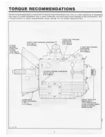
Page 10: ...nded torque ratings Oo not torque capscrews dry 6 FRONT 8EARING COVER CA P SCREWS l 2 0 l 8 FT tlie 18 THREAD 9 SHIFT RAii AETAJNER CAPSCRE W 4 SHIFT LEVE A HOUSING CAJ SCAEWS 20 2 l8S Ft 20 25 l8S FT lilt 16 Tl1READ 0 2 HAtfO HOLE COYIER CAP SCREWS 5 l8 Ft 12 Tl lflEAD THREAD 4 C lUTCH HOUSIHG CAPSCR W 14 155 lBS FT 16 THREAO 8 1 11 HIFT BAR HOUSING CAP CAEWS 2 25 L8 F T _ TitAEAO OUTPUT SHAFT NU...

Page 11: ... l8S Ft 1 18 THREADS C c IJtll I 4 COUNTEASHAF T REAR BEARING COVER CAPSCA WS 20 30 L8S Ft 1e THREAO USE PlAIM FLAT WASHERS 9 OU DRAIN PLUO 20 25 LBS FT it PIPE THREAD o Oil Fill PLUG 20 25 LBS Ft PIPE THREAD 2 COUNTERSH AFT REAR BEARING CAP SET SCREW 5 10 L8S n 1t TH RE AO NOTE APPLY LOCTITE 2 t TO THAEAl S OF ALL CAPSCAEWS 8E F OAE IN 1All INQ ...

Page 12: ......

Page 13: ...oh would ca use oll leakage See TORQUE RECOMMENDATIONS b Check PTO opening and rear bearing cov era for oil leakage 7 Gear Shift Lever a Check tor looseness and free play in hous Ing If lever fs loose In housing proceed with Check No 8 II 8 Gear Shift Lever Housing Assembly a Remove ihe gear shlf1 lever housing as sembly from lransmisslon b Check tension spri ng and washer for set and wear c Check...

Page 14: ......

Page 15: ... cartler worn 11 contact pads 2 Check pedal shalt Replace those worn at bu1hlog surfaces H SHIFT BAR HOUSING ASSEMBLY 1 cneck lor wear on shift yokes and finger n at pads and lever sloL Aeptac xc alvtly worn parts 2 Qieck yokes for correct allgnment Replace 1prung yokes 3 Chick k ckscrew tn yoke asaembly r tatner 1 111tl T gh1ett those found too e I GEAR SHIFT LEVER HOUSING ASSEMBLY 1 Check spring...

Page 16: ... for mlMn halt gears Ing use Loctite 262 l hread ae111n1 on 111 caoscrews For IO Que rat ngs aee TOROUE REC OMMENDATIONS 3 SHIMS Apply a coal of loct t 510 10 bOlh ot ahlms before fin aJ tnste1 110n 10 ptevent 4 ASSEMBLY Refer to the lllus1ra1lon1 provtded in th detailed disassembly 1ns1ruc11ons as e guide 10 reu1embl y 7 SEARINGS Use ot a a eeve lype drrvet lhat con tacts ttte iriner ace of the b...

Page 17: ...ur ca pscrews anct remove 1ower as sombty and gasket from shift bar housing LEVER ORIP OUST COV ER SPRINO 2 Remove shift fever grfp end boo1 from shlfl lever secure assembly in vise with bottom ot housing up Use a large screwdriver to twlst between spring and housing forcing spring trom under lugs In housing Do one coll at a lime ...

Page 18: ......

Page 19: ... HOUSING ASSEMBLY con t 3 lo1 taU tension spring under lugs In housing seating one coil a1 a lime Use of a spring riving tool Is rec ommended 17 4 Remove assembly lrom visa and Install rubber bool over oeacshit1 ever and against housing Install shltl lever grip ...

Page 20: ...EMBLY AND REASSEMBLY SHIFTING CONTROLS SHIFT BAR HOUSING ASSEMBLY e CAPSCAEW EYE t 4TH 5TH SHIFT YOKE 18 _a fil CAPSCREW ill LIFTINO EYE ASK T REVERSE SHIFT YOKE 1a i l MIOOLE RETAINER 1 CAPSCREW __ SNAP AiNQ ...

Page 21: ...d Dlaaasembly _ If t 1 Shlll 1 ronsm1as1on Into neutral potltlon turn out 3 Aemov 1St tevetae yoke assembly capscrew1 end Hit shift bar houting ond gasket trom c1se t 2 Uy arut1 bar hOuS4ng on woric bench u ahown Remove cepscrews and retainers 4 Remcwe 2n0 3fd yokt usemblr ana int erlock pin ...

Page 22: ...I I ...

Page 23: ......

Page 24: ......

Page 25: ......

Page 26: ......

Page 27: ...ND CLUTCH HOUSING Yoke and Clutch Housing A Removel of Yoke 1 lock lhe 1ransmisslon by engag1ng 1wo malnshaft 2 Remove yoke from output shatt gears inset Use a large breMer bar to 1urn Ille nut from 1he output shaft ...

Page 28: ......

Page 29: ......

Page 30: ... ...

Page 31: ...I ...

Page 32: ...ISASSEMBLY TRANSMISSION 8 Remove snap ring Inset thrust washer end toca1 Ing ball 10 Remove 3rd 6peed synchronizer cup and 2nd 3rd speed synchronizer 9 Remove 3rd gear bearings and spacer lrom main shaft ...

Page 33: ...K 1 j 11 Remove snap ring lnS Ot and 2nd 3rd shill hub 13 Remove snap ring Ins et 1hrust washer and IO eating ball I ti 12 Remove 2nd gear bearings and specer from 14 Remove 1st gear bearings and spacer from main mainshalt shaft 31 ...

Page 34: ...ION i 15 Remove 1111peed synchtonJzar 4 17 Using a pullet ln11t 1emove reverse gear washet and rear beating N I 16 Aeooanlon mainshafl in vise rear ot 1h1l1 fac no 18 Remove rENerM geilr bearing and spacer from up main haft ...

Page 35: ...i t 2 0 P J BEARING BEARING CUP CONE l WAS ER Af K f ef BEARING CONE COUNTERSHAFT COUNTE RSMAFT 2ND OE AA 0 lf Q 1 Tutn out four capscrews remove coun1ershaft rear bearing cover and gasket 2 Turn oul 1wo set screws inset Remove bearing retainer outer race and sh1ms NOTE Countershaft may slide to the rear and oul ol bearing bofe ...

Page 36: ...is exposed Inset 4 Remove reverse Idler bearings sp ltcer and lhrvsi washers 6 Move countershafc assembly to the rear and lift t1 from 1h case 6 If countershafl Iron bearing race ts 1o be re placed drive bore plug through front of transmis sion and drive 1he race to Che rear toward the inside of lhe case ...

Page 37: ......

Page 38: ......

Page 39: ...aft long gear to rear ot shaft 37 3 Install 4th and 5th speed gear keys on coun lershaft h1se1 Allgn keyway of 4th peed gear to key on shaft Press 4th gear on long hub of gear 10 tron1of shaft 4 Remove 5th speed key from countershaf1 and In stall spacer lnsel Re tnstaJI key and align key Vay of 5th speed gear with lcey on countersnatt Ptess 5th speed gear on shaft long hub of gear to rear ot shaJt...

Page 40: ...1 Utt fOf furthet 1ntormalion 6 Using a a111ve l PI driver Install front coun terahal1 beaftng shown 311 7 Using a tlffVI type a river Install tarthlft beM1ng as shOwn rear coun a If pr1 1ou1ly r1mowed Install snap ring coun tetahat1 front beartn g race from i nSide ot case ar CI bOre plug_ Coat outer C wneter of bOte plug with Loc1111 510 before tnstatttng NOTE Sl l P ring should be tnstalled wit...

Page 41: ...wer coun1orsheift Into case I I 10 Turn tranamluk n c on ena as she lltn Pos i IK n coun11tthat1 auembly 1n10 front bearing race 39 11 Use oreaM on rnerse tdler thrust washers 10 hold In pl1c1 Po1t1ion tangs ol washers In groo o ot nouatng ...

Page 42: ...rough case and Idler gear bearings Line up notch in shafl with notch In case install lock ball and driv shaJI Into posl tion Inset O I 14 Install eounlershafl rear bearing race into cas e BS Sh0 10 15 Temporarily Install new shims into bearing re tal ner Inset lnstaill retainer Tighten set screws 10 5 10 lbs fl 7 14 Nm NOTE Lube hole in retainer must fine up with lub hole in Ca e ...

Page 43: ...more end play and romove shims or tess end play NOTE Once end play is correct remove re1alner and apply a lighl coat of Loc lite 510 to face of re 1alner Coat threada of set Cte vs with Loctite 262 and retorque 17 Install countershafl rear bearing cover gaskeL Coal threads ot capscrews wi1h Loctite 262 and torque lo 2Q 30 lbs ft 27 41 Nm NOTE Tip tranamis sion 10 horizontal position to install mai...

Page 44: ...fl In vise equipped with wood or brass jaws rear of malnshafl facing up Lubricate and instaJI reverse gear bearings with spacer be 1ween bearings as shown 2 Install majnshaft reverse gear c1utching teeth ol gear lacing down 3 tnstall reverse gear washer Washer can be In s1alled either WfJ Y ...

Page 45: ...with front ol m shaft facing up lubric ale friction surface with lransmisslon lube and install 1st speed synchroni zer 6 Lubricate and lnstaJI 1st goar bearings and spacer lnse1 Install 1st gear clutching 1ee1h facing down 7 Install localing ball and Va sher Washer can be in stalled either we y Install snap ring as shown In ...

Page 46: ...rd clutch llub with stepped tac e of hub facing up ln1111111n1p ring In groove of rnaln shalt lnsel to Lubr cate friction surlece wtth transmission lube and 1n1111t nc t 3td speea synehronizer and 3rd sPff T eynchronw r cup_ _ 11 Lubrfcate and Install 3rd QeBr bearings and sPa cor lnsot ln1tall 3rd gear clutching teeth racing down 4 ...

Page 47: ... Lubricate and Install 4th oear tiearfngt and spa cer Install th gear c Julc hlng lttlh f cing up 14 Install th 5th clutch hub with shoulder en I ot hub taol ng dOwn t s 15 Install 4th speed 1ynchronlzer cup Inset Lubrl cate friction surface with transmission lube and Install 4 1Mith speed aynchrontzer assembly and 5th speed cup ...

Page 48: ...ll snap ting In groove on end ot h fl inset 17 Remove mainshaft assembly Itom vise and place on bench Shift synchronize into 3rd gear 18 Using a sting or rope around the 2nd 3rd syn chronizer aarefully lower malnsha11 Into case 4 19 Using a sleeve lypo driver install bearing on In PUI shaft ...

Page 49: ......

Page 50: ...e nul to 31J0 350 lt s It 407 475 Nm t totate Input shafl and malnshaft lo seat bearings and 1aces 26 Position dlaJ Indicator as shown Pry up on out put shatl to measure end play End play must be se1 et 002 008 0 05 0 20 min Add shims for more end play remove shims tor less end play NOTE Once end plaiy fs correct remove yoke and rear bearing cover and eppfy a light coat of Loctite 510 to both side...

Page 51: ...ASSEMBLY TRANSMISSION 28 Install tear bearlng cover and shlrns Tighten nuts to 60 70 lbs tt 81 95 Nm Top of rear bearing covet Is marked ror p1oper Installation lns1all spoedometor driven gear and sleeve ...

Page 52: ...Position clutch housing on front of lransmlssion Install lour relalning bOlls and torquo to 145 155 Ibo fl 196 210 Nm B lnstallatlon of Yoke 1 Lock the tr 1nsmlssion by engaging two mainshaft gears lnset Carefully lnstall yoke and nut r ighten nut to 300 350 lbs ft 407 475 Nm ...

Page 53: ...using In neutral and Install on case meking sure shift yokes allgn with corresponding synchroni zers and slidi ng clutch I 2 Apply Loctite 262 to thread of capscre vs Install two capscrew into alignment holes of shlfl bar housi ng and torque to 20 25 lbs ft C27 34 Nm 4 3 Install remaining capscrews and torque lo 20 25 lbs ti 27 34 Nm ...

Page 54: ...the neutral poslllon Install gasket and gea1 shift lever ass e1nbly on the shifl bar housing Rt gear s hlll lever in corre sponding finger assembly in bar housing as lever ls Installed 2 Coat threads of retaining capscrew with Loctile 262 and install Torque capscrews to 20 25 lbs II 27 34 Nm ...

Page 55: ...OPTIONS REMOTE CONTROL SHIFT SHAFT SHIFT INOEA WASHER OPTIONAL A A 521 95 MM 3316281 130 MM I NOTE USI 1Kkwir1 M HOUSING ASSEMBLY l OUS NO ...

Page 56: ......

Page 57: ......

Page 58: ...ducts with all options installed Although every attempt has been made to ensure the accuracy of information contained within Eaton makes no representation about the completeness correctness or accuracy and assumes no responsibility for any errors or omissions Features and functionality may vary depending on selected options F or spec ing or service assistance call 1 800 826 HELP 4357 or visit www ...

Reviews: