4
Installation and User manual for the
conventional range of fire panels
EATON
www.eaton.com
Technical Data
PR000-00-513-05
Effective
January 2018
Sounder Wiring
The standard 2 and 4 zone fire alarm control panels have two
separately protected, line monitored, sounder circuits for use with
polarised and suppressed bells, sounders, strobes, relays etc .
The 8 zone fire alarm control panel has four separately protected,
line monitored, sounder circuits for use with polarised and
suppressed bells, sounders, strobes, relays etc .
The wiring for each sounder circuit is to be a parallel circuit with
the 6K8, end of line resistor (EOLR), fitted at the end of the
installed sounder circuit wiring . No ‘spurs’ or ‘tees’ permitted .
Fault/Fire Relay (2-zone & 4-zone)
The 2 & 4 zone panels have one auxiliary relay fitted that provides
a fused volt-free set of change over contacts . These contacts are
not monitored .
The relay has been designed to ‘fail-safe’, so that in the event of
total loss of power the relay contacts will be active .
The auxiliary contacts are fuse protected at 5 Amps (F2) and rated
at 30V dc .
The wiring connections can be found on the main board and are
labelled ‘Auxiliary Circuit’ .
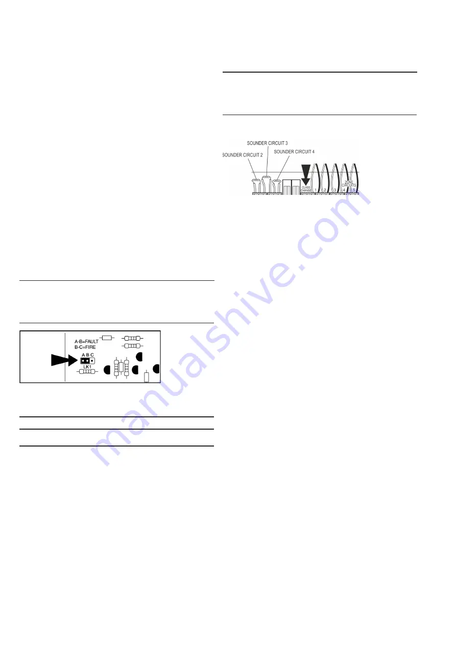
The auxiliary relay is factory configured as a fault relay but can be
configured to operate as a general fire relay using LK1 (Figure 7) .
This can be found on the display PCB and will need to be removed
from the door in order to gain access to it .
LK1
Mode
Panel
Healthy
Panel in
Fault
Panel in
Fire
Position
AB
Fault
Relay
Continuity
between C
and P2
Continuity
between C
and P2
Continuity
between C
and P1
Position
BC
Fire Relay Continuity
between C
and P2
Continuity
between C
and P1
Continuity
between C
and P2
Figure 7. 2 & 4 zone panel Auxiliary relay
CAUTION
POWER DOWN THE FIRE PANEL BEFORE YOU CHANGE ANY
RELAY SETTINGS
J1
Mode
Panel
Healthy
Panel in
Fault
Panel in
Fire
Not Fitted
Fault
Relay
Continuity
between C
and N/C
Continuity
between C
and N/C
Continuity
between C
and N/O
Link Fitted Fire Relay Continuity
between C
and N/C
Continuity
between C
and N/O
Continuity
between C
and N/C
Figure 8. Class change input


