background image

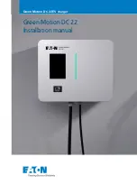
Green Motion DC 22  

Installation manual

Green Motion DC 22 EV charger

Summary of Contents for Green Motion DC 22

Page 1: ...Green Motion DC 22 Installation manual Green Motion DC 22 EV charger ...

Page 2: ...SS FOR A PARTICULAR PURPOSE OR MERCHANTABILITY OTHER THAN THOSE SPECIFICALLY SET OUT IN ANY EXISTING CONTRACT BETWEEN THE PARTIES ANY SUCH CONTRACT STATES THE ENTIRE OBLIGATION OF EATON THE CONTENTS OF THIS DOCUMENT SHALL NOT BECOME PART OF OR MODIFY ANY CONTRACT BETWEEN THE PARTIES In no event will Eaton be responsible to the purchaser or user in contract in tort including negligence strict liabi...

Page 3: ...1 Front and back views 7 3 2 Left and right views 8 3 3 Top and bottom views 8 3 4 Types of cables 9 4 RELEVANT INFORMATION PRIOR TO THE INSTALLATION 10 4 1 Tools required for the installation 10 4 2 Package contents 10 4 3 Dimensions and weight 11 4 4 Lifting transportation and unloading instructions 12 4 5 Unpacking 12 5 MOUNTING AND INSTALLATION 13 5 1 Positioning the Green Motion DC 22 EV char...

Page 4: ...line station 32 7 3 How to start charging 32 7 4 Indicators and user interfaces 32 7 4 1 LED indicators 33 7 4 2 Color touchscreen display 34 7 5 Emergency stop button 35 8 MAINTENANCE 36 8 1 How to open close the Green Motion DC 22 housing 36 8 2 How to set the unit as out of order 37 8 3 Replace the SIM card 38 8 4 Cleaning or replacing filters 38 8 5 Dismount 39 8 6 Station updates 39 8 7 Dispo...

Page 5: ...on cannot be held legally accountable The contents of this manual are the copyright of the publisher and may not be reproduced even in extracts without the prior written approval of Eaton While every care has been taken to ensure the accuracy of the information contained in this manual Eaton assumes no liability for any error or omission Eaton reserves the right to modify the designs of its produc...

Page 6: ...neous charging 1 Options Cable CHAdeMO Floor mounted Floor mounted with a pedestal Network interface 3G 4G Software licenses Eaton Scan Charge Eaton Charging network manager Warranty Warranty 2 years 1 2 Symbols used in this manual An electric shock can be fatal Avoid touching internal or external parts normally live while the system is powered on Read the instructions These instructions are inten...

Page 7: ...ription AC Alternating current CAN Controller Area Network CCS Combined Charging System CHAdeMO CHArge de MOve DC Direct current EMC Electromagnetic compatibility EMI Electromagnetic interference FW Firmware HW Hardware IEC International Electrotechnical Commission IP Internet Protocol LAN Local area network LCD Liquid crystal display N Neutral OV Overvoltage PE Protective earth PPE Personal prote...

Page 8: ...vices is extremely dangerous and relieves the manufacturer of any responsibility for damage caused to people and property A first aid kit must be provided near the installation site so that it is readily available in case of emergency 2 1 Operating environment and restrictions Each system must be used exclusively for the operations it was designed for and within the operative ranges specified in t...

Page 9: ...d according to the intended use The responsibilities deriving from the commercial components are delegated to the respective manufacturers Avoid touching the equipment housing during the equipment operation The housing could overheat during its operation or be heated by direct sunlight To avoid burns from an overheated surface caused by sunlight please use suitable PPE or wait for the equipment to...

Page 10: ...Table 3 Residual risks Risk assessment Recommended solution Noise pollution caused by installations in unsuitable environments or where professionals work on a regular basis Reassess the installation environment or site Unsuitable ventilation in the location causing equipment to overheat leading to discomfort for people who are on the site Restore adequate ambient conditions and ventilate the site...

Page 11: ...he Green Motion DC 22 EV charger 3 General description 3 1 Front and back views Figure 1 Front and back views of Green Motion DC 22 EV charger Tag Description 1 Color touchscreen display 2 RFID reader 3 LED indicator 4 Cable glands 5 Mounting holes 35 mm 1 4 inch 440 mm 17 3 inch 45 mm 1 8 inch 49 mm 1 9 inch 532 mm 20 9 inch 5 5 5 5 3 4 RFID 1 2 ...

Page 12: ...tion DC 22 EV charger 3 2 Left and right views Figure 3 Top and bottom views of Green Motion DC 22 EV charger Tag Description 1 Power input cable gland 2 Ethernet cable gland 3 CHAdeMO cable gland 4 CCS cable gland 5 Optional cable entries knockout holes 6 Screws to open close the front door 7 Emergency stop button Tag Description 1 Air flow grid 1 1 5 5 2 6 6 3 7 4 ...

Page 13: ...he actual charging power may vary due to external factors such as the available grid power capacity of the electrical installations and EV model For this reason Eaton disclaims any liability concerning the actual power output Figure 4 Illustration of connector types available with Green Motion DC 22 EV charger Tag Description 1 CCS Type 2 2 CHAdeMO The unit can be equipped with either CCS or both ...

Page 14: ...ional and qualified personnel During the installation ensure the equipment is powered off 4 2 Package contents To perform installation professional and qualified personnel should have the following tools The Green Motion DC 22 box must contain the following parts Screwdriver T20 TX30 PZ2 Open ended wrenches Drilling machine depending on the mounting surface Laptop SIM card in case of online charge...

Page 15: ... in kg 53 Column Column dimensions H x W x D in mm 1080 x 540 x 200 Column weight in kg 32 Cables CCS weight in kg 4 CHAdeMO weight in kg 6 Total Total height in mm 1600 Total weight in kg max 96 Figure 5 shows the front and side views of the EV charger with dimensions together with the optional floor mount pedestal Figure 5 Green Motion DC 22 EV charger front and side views with dimensions 630 mm...

Page 16: ...herwise stated The unit is not equipped with specific lifting tools Remember that the packaging elements cardboard cellophane staples adhesive tape straps etc can cut and or injure if not handled with care They must be removed with appropriate tools and must not be handled by non responsible people i e children The packaging components must be removed and disposed of in accordance with the local r...

Page 17: ...es of the unit to allow for adequate air circulation The cable entries for power cables and the internet connection cable are through the bottom or rear of the charging station The product can be wall mounted or floor mounted with a column optional 5 2 1 Site design A site for electric vehicles EVs equipped with charging stations can be designed in different setups This section is intended to prov...

Page 18: ...ure 6 Optimal positioning of EV chargers Alternative positions for the EV chargers are shown in Figure 7 If a wall is not available for mounting it is possible to use a floor mounted column Figure 7 Alternative positioning of EV chargers Tag Description 1 EV charger Tag Description 1 EV charger 1 1 1 1 1 ...

Page 19: ...bottom side of the EV charger See Section 6 2 for details Please note that the appropriate types of plastic plugs and screws must be selected by professional and qualified personnel based on the following considerations the location of installation and the type of the wall on which the system is to be mounted Recommended screws stainless steel Ø6 x 50 mm min In case of obstacles such as snow or si...

Page 20: ...ace the four gaskets on the back of the charging station Figure 9 Details of gaskets on the back of the EV charger with dimensions Step 2 Install the four selected screws with flat washers into the wall leaving them to protrude 10 mm from the surface see Figure 10 Step 3 Mount the unit onto the screws temporarily using them as holders Figure 10 Installation site with the protruding screws 35 mm 1 ...

Page 21: ...or to the left side of the EV charger depending on site configuration and user preferences Consider a 300 mm free space requirement to the left and right side of the EV charger for air circulation Position the plug holder s very carefully ensure that the polarizing keys are on the top side of the plug holder before fixing the plug holders to the wall with screws See Figure 12 Mount the plug holder...

Page 22: ...ly screw the plug holder onto the metal cable support see Figure 12 Figure 12 View of the CCS and CHAdeMO plug holders respectively Tag Description 1 Polarizing keys 2 Fixing screws 3 Metal sheet cable support 4 Wall A CCS plug holder Front view B CHAdeMO plug holder Front view C CCS plug holder Side view D CHAdeMO plug holder Side view 60 mm 2 3 inch 75 mm 2 9 inch 2 103 mm 4 0 inch 118 mm 4 6 in...

Page 23: ...able Below is a schematic representation of the base of the EV charger column to be mounted on the concrete base Figure 13 The base of the EV charger column with dimensions Tag Description 1 Concrete base 2 Hole for electrical cables 3 M10 stainless steel threaded rods A Top view of the concrete base B Overview of floor mounted pedestal on concrete base When choosing the location of the floor moun...

Page 24: ...the floor mount pedestal Step 1 Place the 4 gaskets on the back of the EV charger Step 2 Fix the unit to the backplate of the pedestal with 4 stainless steel M6 screws as described in Figure 15 Figure 15 How to fix the unit on the backplate of the floor mount pedestal 440 mm 17 3 inch 532 mm 20 9 inch 532 mm 20 9 inch 440 mm 17 3 inch 200 mm 7 8 inch Be careful not to break the emergency stop butt...

Page 25: ... stainless steel M6 x 10 screws 4 serrated lock washers 4 flat washers and 2 prevailing torque type hex lock nuts to the pedestal Once the EV charger is mounted on the column fix the plug holders to the cable supports on the sides of the pedestal Plug holders can be mounted to the right and or left side of the EV charger depending on site configuration and user preferences Position the plug holder...

Page 26: ... com 00 Title Figure 18 Front and lateral views of the EV charger and plug holders mounted on the froor mount pedestal 630 mm 24 8 inch 265 mm 10 4 inch 200 mm 7 8 inch 520 mm 20 4 inch 1080 mm 42 5 inch 1600 mm 62 9 inch 540 mm 21 2 inch 440 mm 17 3 inch 398 mm 15 6 inch 324 mm 12 7 inch ...

Page 27: ... Table 6 Overview of parameters for dimensioning of the protective devices and power supply line Green Motion DC 22 EV charger nominal power range 22 kW Nominal input voltage Un Uph 230 V 400 V Nominal input current 32 A Phases 3 phase Power supply terminal block max section 16 mm The power losses on the power supply line must be less than 10 of the rated power in accordance with IEC 60038 and loc...

Page 28: ...ed with an RCD upstream in accordance with IEC 60364 7 722 Eaton s support teams can help with the selection of the proper RCD to be used In case of connection in TN C S networks earth rods must be used It is not possible to install the unit in an IT grid configuration Always refer to local regulations which may differ from and can supersede the international regulations listed above The circuit b...

Page 29: ...een Motion DC 22 EV charger Type Eaton Article number 40 A breaker for the three phase 32 A charging current FAZ C40 3N 278979 A detailed connection diagram of the Green Motion DC 22 EV charger is in Figure 20 where output for power supply and charging cables are shown Figure 20 Detailed connection diagram of the EV charger with external output of power supply and charging cables Tag Description 1...

Page 30: ...e and three possible knockout holes for the ethernet cable as shown in Figure 21 Holes numbered 1 and 4 in Figure 21 are intended for use with a floor mounted EV charger To feed the cables into the EV charger knock out one of the holes for the power cable and one for the Ethernet cable Before starting the connection operations ensure the external AC line main switch is disconnected and circuit bre...

Page 31: ...re the EV charger to the power supply Figure 22 AC grid connectors inside the Green Motion DC 22 EV charger L1 L2 L3 N PE Connect the three phases L1 L2 L3 neutral N and earth PE cables to the GRID terminal block respecting the correct assignment Phase L1 L1 terminal Phase L2 L2 terminal Phase L3 L3 terminal Neutral N N terminal Earth PE PE terminal Be careful not to reverse the phases with the ne...

Page 32: ... 6 4 Earth connection MANDATORY Check if the ground wire between the door the housing and the protective conductor of the Green Motion DC 22 EV charger is properly attached See the connection instructions shown in Figure 23 Figure 23 Ground wire between door and housing and to protective conductor PE ...

Page 33: ...cal regulations Step 4 Perform checks on the continuity of the connections of the protective conductor insulation resistance RCD triggering current triggering time etc in accordance with local regulations Step 5 Verify that the front door is closed and secured with the fixing screws If the checks listed above were successful proceed as follows Step 1 Close the main AC GRID circuit breakers Step 2 ...

Page 34: ...he router of the EV charger must be performed by professional and qualified personnel who are responsible for complying with existing standards and local installation regulations WARNING Any operation requiring the opening of the charger can lead to electric shock hazards Please refer to Chapter 8 1 of this manual to open the Green Motion DC 22 EV charger housing It is possible to configure the ne...

Page 35: ...op is below the same subnet of the RUTX09 router The default IP address of the router is 192 168 52 1 The default IP address as well as the login credentials can also be found on a printed label on the router unit Step 3 Connect to the router If a step by step configuration menu Setup Wizard appears ignore it and go directly to the menus described below Step 4 Go to the Network WAN menu Step 5 Act...

Page 36: ... contact your Eaton service representative Figure 28 Example of a SIM card Always make sure the EV charger is on standby mode before inserting or removing the SIM card Follow the steps below to configure the modem router of the unit for connection via SIM card Step 1 Connect your laptop with one of the LAN ports of the router via an ethernet cable See Figure 29 Figure 29 Teltonika RUTX09 modem rou...

Page 37: ...s used it is mandatory for the user to select the plug on the screen Refer to the next section If the card is not authorized the charging will not start and a red triangle is displayed on the charging station status display See Chapter 7 4 If the charging cable is disconnected from the car and there is no power consumption within two minutes the user is automatically deauthenticated 7 4 Indicators...

Page 38: ...n Ready for use Flashing green light Start up stage Breathing green light Waiting for user interaction Flashing blue light Charging session start up Breathing blue light Charging session in progress Blue light on Charging session completed Red light on Error in charging No light Stopped or not powered During charging the LED indicator shows the state of charge of the vehicle as illustrated in Figu...

Page 39: ...n display Display Description Touchscreen display Touch the screen to wake up Authentication screen Before any operation ensure that the 4G sign is colored in blue If the bar graph is RED there is no connection to the server Choose your language by touching the flag Place the RFID badge on the RFID reader to initiate authentication Select the appropriate plug State of charge of the vehicle Authent...

Page 40: ... per Figure 29 Push the button in cases of emergencies Figure 31 Location of the emergency stop button Tag Description 1 Emergency stop button After checking that there is no more risk turn the button located under the terminal to turn off the emergency stop button Unplug and reconnect the vehicle to correct the error Charging station is already booked by a user If you are not the one who booked i...

Page 41: ...ow to open close the Green Motion DC 22 EV charger housing When removing the front door be careful not to damage any cables connected to the display and the electronics boards Before attempting to open the EV charger ensure the external AC line main switch is disconnected and circuit breakers are open Follow these steps to open the housing of the EV charger Figure 32 Location of the screw at the t...

Page 42: ...screw the screw located on the bottom right side of the EV charger using the T20 screwdriver Step 3 The front door can be opened sideways 8 2 How to set the unit as out of order The Green Motion DC 22 EV charger can be set as out of order by following the steps below 1 On site method Press the emergency stop button 2 Remote method Access the Eaton Charging network manager and set the unit as out o...

Page 43: ...e Figure 35 Please make sure that the fans are turned off and that the EV charger is not in use during the maintenance operation Moving fans can be dangerous and cause finger injuries Please make sure the filters are checked on a yearly basis to ensure they are not obstructed and working properly In case of obstruction filters need to be replaced as soon as possible In case of obstruction Eaton re...

Page 44: ...U standard EN 50419 for marking of electrical and electronic equipment we include the crossed out wheeled bin symbol on our products This symbol alerts users that these products should be recycled in accordance with local environmental regulations and not discarded with household waste When end users recycle WEEE they are helping to ensure that they are neither incinerated nor sent to landfill min...

Page 45: ...he indication display on the screen Try to disconnect the car from the EV charger and retry Check the emergency stop button it should be pulled out Antenna bar graph is red Check the led status color and read the indication display on the screen Check that the connection of the EV charger to the backend is available network is available Authentication refused Check the led status color and read th...

Page 46: ...not replace those that appear on the rating plate attached to the equipment The labels attached to the equipment must NEVER be removed damaged soiled or hidden for any reason The information displayed on the rating plate 1 Manufacturer 2 Model 3 Ratings 4 Certification marks 5 Warnings 6 Serial number The labels must NOT be hidden with foreign objects rags boxes equipment etc they must be periodic...

Page 47: ...9 1 and IEC 61439 7 Cable Version IEC 62196 1 and IEC 62196 3 Electromagnetic compatibility Product IEC 61000 6 1 and IEC 61000 6 3 IEC 61000 3 11 and IEC 61000 3 12 Communication ISO 15118 DIN 70121 CHAdeMO 0 9 1 2 Table 11 List of standards the Green Motion DC 22 EV charger complies with 11 Contact support information Should any technical problems arise during the operation of the charging stati...

Page 48: ... All trademarks are property of their respective owners Eaton Industries Manufacturing GmbH Place de la Gare 2 1345 Le Lieu Switzerland Eaton com greenmotiondc22 2022 Eaton All Rights Reserved Publication No MN192004EN November 2022 ...

Reviews: