2
ARTICLES REQUIS :
(à acheter séparément)
• Tournevis cruciforme
• Clé à molette ou clé à rochet avec douille de 10 mm
• Perceuse avec foret de 3/16 po
• Conduit d’un diamètre de 1/2 po (au besoin, longueur selon l’installation)
• Raccords de conduit étanches de 1/2 po (au besoin)
• Capuchons de connexion
IMPORTANTES INSTRUCTIONS DE SÉCURITÉ
Des précautions de base doivent être suivies lors de l’utilisation de ce produit, incluant :
• Le respect de tous les avertissements incluant les avertissements ci-dessous
ET ceux indiqués sur le produit.
• Conservez ces instructions et ces avertissements.
• Exclusivement réservé à un usage extérieur.
• Homologation cULus pour l’utilisation dans des endroits humides.
• Lisez et suivez ces instructions.
• Coupez l’alimentation électrique au fusible ou au disjoncteur avant l’installation
ou l’entretien.
• Les bords peuvent être coupants. Manipuler avec soin.
MISE EN GARDE
• Raccordez le luminaire à une source d’alimentation de 120 V, 60 Hz.
Tout autre raccordement annule la garantie.
• L’appareil d’éclairage doit être installé par des personnes ayant l’expérience du
câblage domestique ou par un électricien qualifié. Le système électrique et la méthode
de raccordement électrique de l’appareil d’éclairage doivent être conformes au Code
national de l’électricité et aux codes locaux du bâtiment.
• Si l’appareil d’éclairage est installé à l’envers, il peut y avoir surchauffe ou
accumulation d’eau. Installez-le à l’endroit.
• Après la mise à l’essai, cet équipement a été déclaré conforme aux limites établies
pour un dispositif numérique de catégorie B en vertu de la section 15 des règlements
de la FCC. Ces limites sont conçues pour assurer une protection raisonnable
contre toute interférence nuisible dans une installation résidentielle. Cet équipement
génère, utilise et dégage de l’énergie radiofréquence. S’il n’est pas installé et utilisé
conformément aux instructions, il est susceptible de créer des interférences nuisibles
aux communications radio. Toutefois, il n’est absolument pas garanti qu’aucune
interférence ne se produira dans une installation donnée. Si l’équipement crée
des interférences nuisibles à la réception d’émissions de radio ou de télévision (pour le
savoir, allumez-le et éteignez-le), il est conseillé à l’utilisateur d’essayer d’éliminer ces
interférences en adoptant une ou plusieurs des mesures suivantes :
- Réorientez ou déplacez l’antenne réceptrice.
- Augmentez la distance entre l’équipement et le récepteur.
- Branchez l’équipement sur la prise électrique d’un circuit autre que celui sur lequel
le récepteur est branché.
- Demandez de l’aide au distributeur ou à un technicien radio ou TV qualifié.
AVERTISSEMENT : Les réglementations de la FCC mentionnent que toute
modification ou altération apportée à cet équipement n’étant pas expressément
approuvée par le fabricant peut annuler le droit de l’utilisateur à faire
fonctionner cet équipement.
CONSERVEZ CES INSTRUCTIONS.
MONTAGE ET CÂBLAGE DE L’APPAREIL D’ÉCLAIRAGE
REMARQUE :
Cet appareil d’éclairage a été conçu pour le raccordement en conduit à un
boîtier de jonction en métal étanche, mis à la terre et adéquatement installé (non inclus).
Tous les conduits, raccords et boîtiers de jonction (vendus séparément) doivent posséder
l’homologation cULus pour l’utilisation dans des endroits humides.
1.
Coupez le courant à la boîte de fusibles ou de disjoncteurs principale.
2.
À l’aide du gabarit du boîtier, marquez et percez les trous de montage.
REMARQUE :
Cet appareil d’éclairage doit être installé en position verticale et de niveau.
3.
Installez d’abord les 2 vis de montage du bas (C), en laissant assez d’espace pour
l’appareil d’éclairage jusqu’à la surface de montage.
4.
Vissez la vis de montage du haut (C) dans le trou prépercé, puis dévissez-la.
Cette mesure vise à fileter le trou pour faciliter l’installation de l’appareil d’éclairage.
5.
Retirez la lentille en desserrant les deux vis qui se trouvent à l’intérieur.
Ne les retirez pas complètement.
6.
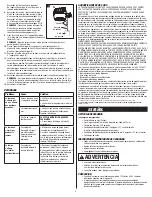
Retirez le cache d’accès (B) de l’appareil
d’éclairage (A). Installez le premier raccord
de conduit et le conduit (vendus séparément)
dans le cache d’accès (B) (fig. 1).
7.
Passez les fils d’alimentation dans le conduit.
FRANÇAIS
AVERTISSEMENT
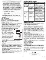
5-YEAR LIMITED WARRANTY
THE FOLLOWING WARRANTY IS EXCLUSIVE AND IN LIEU OF ALL OTHER WARRANTIES,
WHETHER EXPRESS, IMPLIED OR STATUTORY INCLUDING, BUT NOT LIMITED TO, ANY
WARRANTY OF MERCHANTABILITY OR FITNESS FOR ANY PARTICULAR PURPOSE.
Eaton warrants to customers that, for a period of five years from the date of purchase, Eaton
products will be free from defects in materials and workmanship. The obligation of Eaton
under this warranty is expressly limited to the provision of replacement products. This
warranty is extended only to the original purchaser of the product. A purchaser’s receipt or
other proof of date of original purchase acceptable to Eaton. This is required before warranty
performance shall be rendered. This warranty does not apply to Eaton products that have been
altered or repaired that have been subjected to neglect, abuse, misuse or accident
(including shipping damages). This warranty does not apply to products not manufactured by
Eaton which have been supplied, installed, and/or used in conjunction with Eaton products.
Damage to the product caused by replacement bulbs or corrosion or discoloration of brass
components are not covered by this warranty.
LIMITATION OF LIABILITY:
IN NO EVENT SHALL EATON BE LIABLE FOR SPECIAL, INDIRECT, INCIDENTAL, OR
CONSEQUENTIAL DAMAGES (REGARDLESS OF THE FORM OF ACTION, WHETHER IN CONTRACT,
STRICT LIABILITY, OR IN TORT INCLUDING NEGLIGENCE), NOR FOR LOST PROFITS; NOR SHALL
THE LIABILITY OF EATON FOR ANY CLAIMS OR DAMAGE ARISING OUT OF OR CONNECTED
WITH THESE TERMS OR THE MANUFACTURE, SALE, DELIVERY, USE, MAINTENANCE, REPAIR OR
MODIFICATION OF EATON PRODUCTS, OR SUPPLY OF ANY REPLACEMENT PARTS THEREFORE,
EXCEED THE PURCHASE PRICE OF EATON PRODUCTS GIVING RISE TO A CLAIM. NO LABOR
CHARGES WILL BE ACCEPTED TO REMOVE OR INSTALL FIXTURES.
To obtain warranty service, please contact Eaton at 1-800-334-6871, press option 2 for
Customer Service, or via e-mail ConsumerProducts@eaton.com and include the following
information:
• Name, address and telephone number
• Date and place of purchase
• Catalog and quantity purchase
• Detailed description of problem
All returned products must be accompanied by a Return Goods Authorization Number issued
by the Company and must be returned freight prepaid. Any product received without a Return
Goods Authorization Number from the Company will be refused. Eaton is not responsible for
merchandise damaged in transit. Repaired or replaced products shall be subject to the terms
of this warranty and are inspected when packed. Evident or concealed damage that is made
in transit should be reported at once to the carrier making the delivery and a claim filed with
them.
Reproductions of this document without prior written approval of Eaton are strictly prohibited.
For assistance, call 1-800-334-6871 or e-mail us at ConsumerProducts@eaton.com
Printed in China
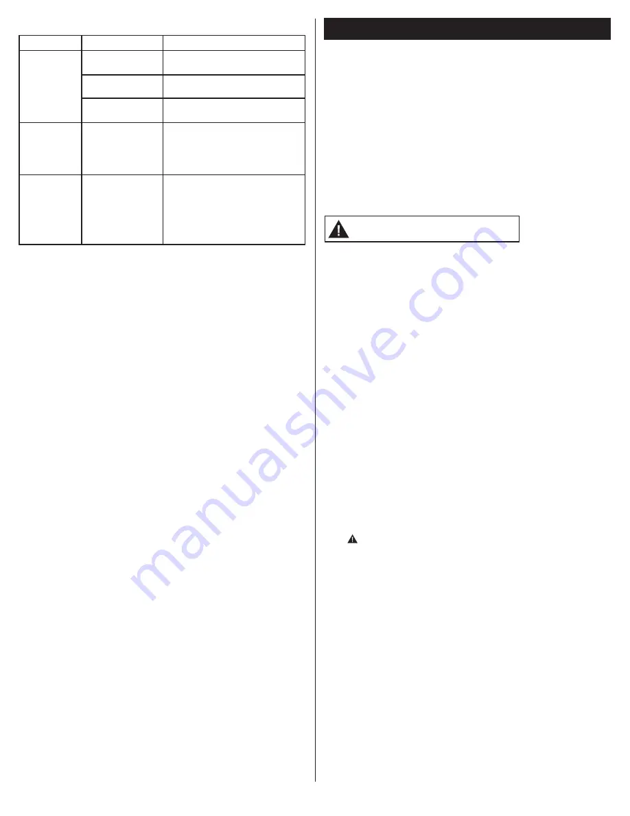
TROUBLESHOOTING
Problem
Cause
Solution
Light does not
come on or
light comes
on for only a
few seconds.
No power to the fixture.
• Check if circuit breaker tripped.
• Confirm wall switch is ON.
Light sensor is not
working properly.
• Check if light is being reflected into the
sensor, causing the fixture to turn off.
Wiring to the unit
is loose.
TURN OFF POWER BEFORE CONTINUING.
• Confirm wiring is properly secured.
Light does not
shut off during
daytime.
Light sensor is not
receiving enough light
to trigger switch.
• Shine a flashlight into the light sensor for
2-3 minutes. The fixture should switch
off after two minutes. This means the
sensor is not receiving enough light;
reposition or relocate the fixture.
Light cycles on
and off.
Light sensor is sensing
reflected light.
• Cover light sensor with a piece of black
electrical tape. The fixture should turn
on after a slight delay. This means that
extraneous or reflected light from the
fixture is causing the sensor to turn the
unit off. Install fixture where there is no
reflective light.


