HMi Series Instruction Leaflet
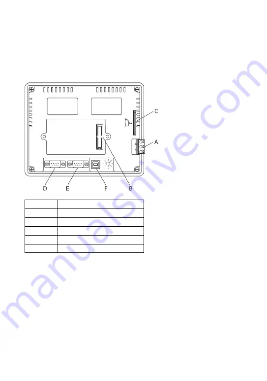
6” HM
i
(HMI06BE/HMI06GE/HMI06CE)
A Power
Input
Terminal
B Expansion
Slot
C
Smart Memory Card Slot
D COM2
(Note)
E COM1
F USB
NOTE
For simultaneous communications, wire one DB9 connector for COM2 and COM3
according to the pinout diagram in this document.
EATON CORPORATION
www.eaton.com 6


