i-on30EXL/EXDL
Installation
Page 27
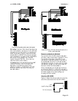
TNV - Telephone line connector.
SELV
– All other connectors.
Figure 52 SELV and TNV connectors
Connecting the Telephone Line
Connecting the telephone line directly to the
terminals on the internal communicator, or
indirectly through other apparatus, can produce
hazardous conditions on the telephone network.
Always seek advice from a competent telephone
engineer if in any doubt about connecting to these
terminals.
Example
– connecting a line in the UK:
The internal communicator must be connected to
the telephone network by:
a) If the wiring is owned by British Telecom:
British Telecom.
b) If the wiring is not owned by British Telecom,
one of:
(i) British Telecom.
(ii) The authorised maintainer.
(iii) A professional Installer, after 14 days
written notice to the authorised
maintainer.
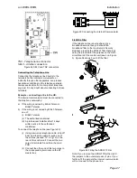
To connect the telephone line (see Figure 53):
(i) Using a two-core telephone cable, strip off
5mm and feed the cable through one of
the entries
(marked “10” in Fig. 2) in the
rear of the control unit. Connect the two
cores to terminals A and B on the main
PCB.
(ii) Connect the other end of the two cores to
the corresponding terminals on the BT
master box.
Figure 53 Connecting the Internal Communicator
Fit ADSL Filter
If the telephone line is being shared by a
broadband service then you should fit a
broadband filter to the line.
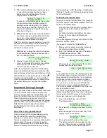
Eaton’s Security
Business provides the ADSL01 filter that plugs
onto pins provided for the purpose on the main
circuit board of the control unit (see 5 on Figure
3). Figure 54 shows how to fit the filter.
Figure 54 Fitting the ADSL01 Filter.
Note: If you remove the ADSL01 filter then re-fit
the jumpers to the outermost pairs of pins. If you
fail to re-fit the jumpers the internal communicator
will not connect to the phone line.


