i-on40
Before You Begin
Page 7
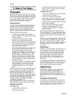
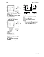
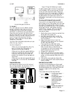
1. Jumpers for addressing and LED function:
1a Addressing
1b LED functions and RS485 terminate
2. Sounder volume control.
3. Tamper switch.
4. Sounder.
5. Connector for control unit.
Figure 12 KEY-K01 Keypad PCB
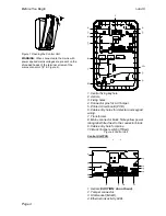
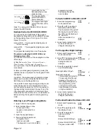
1. Tamper switch.
2. Sounder.
3. Connector for KEY-EP.
4. Sounder volume control.
5. Connector for control unit bus.
6. Jumpers for:
6a Addressing (not used in i-onEX
control units).
6b LED functions and RS485 bus
termination.
Figure 13 KEY-KP01 Keypad PCB
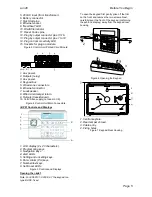
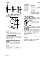
1. Tamper switch.
2. Sounder.
3. Connector for KEY-EP. Terminals for
zones
4. Sounder volume control
5. Connector for data bus and output
terminal.
6. Jumpers for addressing and LED function:
6a Addressing
6b LED functions and RS485 terminate
Figure 14 KEY-KPZ01 Keypad PCB
2
3
4
BRIGHT
TERM
0V 12V A
B
0V 12V D0 D1 LED
EXT READER
Z1 Z2
OP
1
6a
6b
3
4
5
6
2


