i-on40
Installation
Page 17
Step 5. Connect Wired
Peripherals
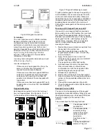
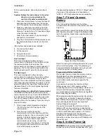
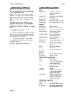
Figure 34 Connecting Wired Peripherals
The control unit PCB provides four connectors for
wired outputs. Outputs 1 and 2 are voltage free
relay outputs. Outputs 3 and 4 are driven by
transistors, and are capable of sinking a maximum
500mA when active. By default outputs 3 and 4
are 0V when active, +12V when inactive. If you
wish to reverse the polarity of these two outputs
use
Installer Menu - Outputs - Wired Outputs – Output
3(4) - Polarity
.
Remote Loudspeaker (Optional)
If you wish to add a 16 Ohm wired Loudspeaker
unit, then connect it as shown in Figure 34. The
control unit provides connections for one
loudspeaker. Do not connect another loudspeaker
in parallel. You may connect another loudspeaker
in
series
, but this will decrease the maximum
volume from the speakers.
Note: Loudspeakers are not warning devices as
described by EN50131-4. Although loudspeakers
may mimic alarm tones, they also give alert tones
and other progress tones when setting and
unsetting the alarm system.
Wired External Sounders (Optional)
Wired external sounders differ in their methods of
connection. Figure 34 shows an example of a
general method of using the outputs to connect a
wired sounder.
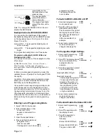
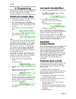
It is possible to program the TR terminal on the
control unit (see item 8 in Figure 4) as either CC
or FSL. Use
Installer Menu – System Options – Panel
Tamper Rtn
. By default the terminal is CC. If you
program the TR terminal as FSL then make sure
you connect a 2k2 resistor in series with the wire
to the sounder.
Note: If you do not wish to connect a wired
external sounder then leave TR programmed as
CC and make sure you link TR to 0V on the
control unit. This prevents the control unit
reporting Bell Tamper unnecessarily.
Wired Outputs (Optional)
Figure 34 shows an example of using the wired
outputs to drive an indicator LED.
Output on KEY-KPZ01
The output on a KEY-KPZ01 is not available for
use with an i-on40.
Step 6. Fit a Plug-By
Communicator
The control unit can be connected to a separate
communicator or speech dialler (for example, the
Scantronic 8400, 8440, 660 or RedCare STU).
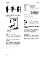
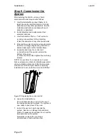
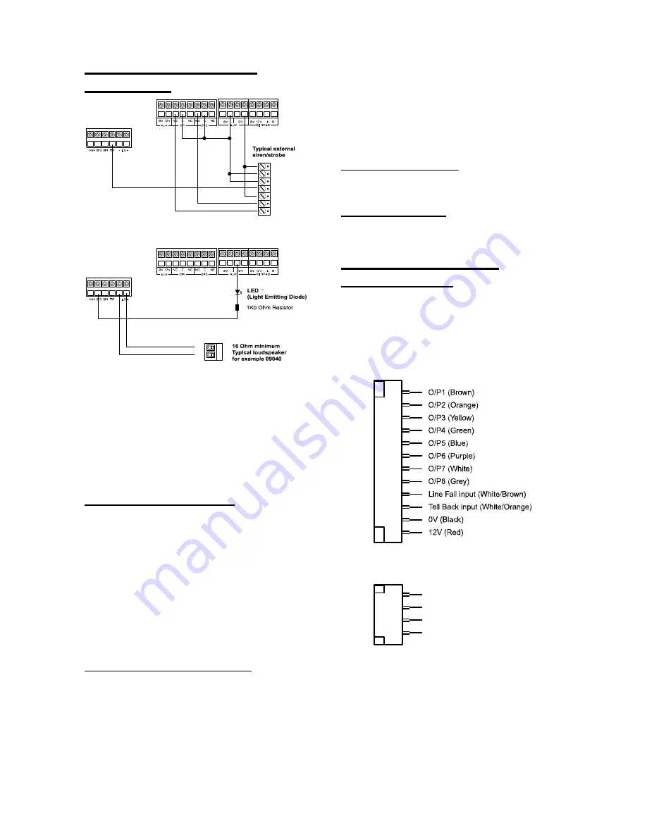
Figure 35 shows the connections provided by the
communications wiring harness.
Figure 35 Plug-By Communicator Wiring
Note: Comms O/P4 will be active when the
system is unset. This is normal.
12V +
0V
Tamper In
Tamper Out
ve
Strobe -ve
Trigger -ve
+LS
-LS
O/P9 (Brown)
O/P10 (Orange )
O/P11 (Yell ow)
O/P12 (Green)
Com Connector Ca ble,
Part number 1196005 8
Com Connector Ca ble,
Part number 48521 0

