DESCRIPTION:
DATE:
DRAWING NO:
SHEET:
REVISION:
B
2 of 2
091504
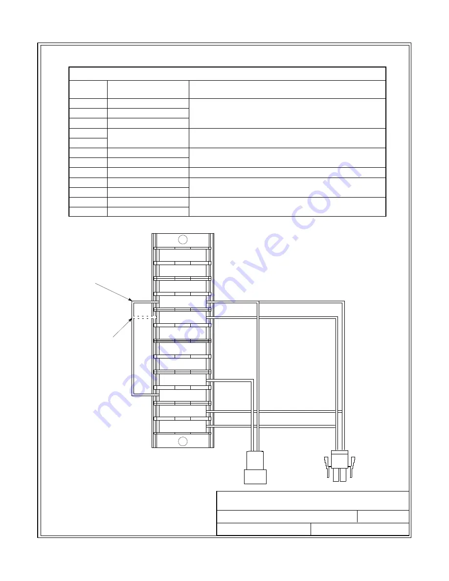
INTERFACE WIRING INSTALLATION
NOTES AND TERMINAL CONNECTIONS
1
2
3
4
5
6
7
8
9
11
10
12
J3
P3
TO UPS OR
PARALLEL
BATTERY
CABINET
TO PARALLEL
BATTERY
CABINET
TB1
FIRST AND MIDDLE
CABINETS IN
MULTI-CABINET
INSTALLATIONS
SINGLE CABINET
INSTALLATIONS AND
LAST CABINET IN
MULTI-CABINET
INSTALLATIONS
Installation Information
A-18
EATON
Powerware
®
9390 Integrated Battery Cabinet (Models IBC-S and IBC-L) Installation Manual
S
164201536 Rev D
www.eaton.com/powerquality
6.
Refer to Table F for TB1 interface connections.
Table F. TB1 Interface Connections
Terminal
TB1
Name
Description
1
CB1 Aux 1 Switch NC
Auxiliary battery breaker dry contacts. Not used.
2
CB1 Aux 1 Switch Com
3
CB1 Aux 1 Switch NO
4
Jumper Tie Points
Single or multi‐cabinet selection
5
6
Battery UVR +
Internal connection to UVR coil.
7
Battery UVR -
8
CB1 Aux 2 NC
Auxiliary battery breaker dry contact. Not used.
9
CB1 Aux 2 Com
Contact used to indicate whether UPS battery breaker or
disconnect is open or closed.
10
CB1 Aux 2 NO
11
Battery UVR -
Contacts used to open battery breaker or disconnect.
12
Battery UVR +


