InsulGard System Installation and Start Up Guideline
8
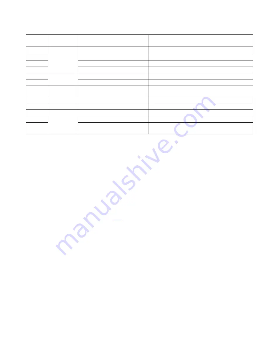
Auxiliary sensor connection table:
Contact
#
Sensor
connected
Sensors wire
Note
1
Temperature
sensor
100 Ohm
Platinum
RTD
RTD common wire (white wire)
Board common
2
RTD signal wire (black wire)
Output dc current ≈ 2mA
3
RTD signal wire (red wire)
Output dc current ≈ 2mA
4
Cable shield (optional)
Board common
5
Load (CT)
sensor
Signal wire (red wire)
Input impedance 100 Ohm,
Max input
signal ≈ 5mA
6
Common wire (black wire)
Board common
7
External
Reference
Usually not used
Input impedance > 27kOhm. Input voltage should
not exceed 1VAC
8
n/a
test point
9
n/a
Board common
10
Humidity
sensor
Sensor common (white wire)
Board common
11
+ 5VDC for the sensor (red wire)
Output current is limited by 100 Ohm resistor.
12
Output signal (black wire)
Input impedance > 27kOhm. Input voltage should
not 5V.
10) PD sensor connection
Coaxial cables from PD sensors should be connected to Ch1-Ch15 inputs (Figure 1-6) on the right side of the
Sensor Interface Board.
Ch16 is designated only for noise signal and usually isn’t used.
Please pay special attention to their connection. InsulGard comes preconfigured for certain sequence of the PD
sensor connection to channels 1-15. PD sensors must be connected accordingly. For motor/generator application
connect IPDS sensors on phases A, B and C starting with channel 1 and then connect RTD PD sensors. For
switchgear application, this sequence is shown in the configuration worksheet that the customer provided to Eaton at
the time of order entry. Settings can also be verified in InsulGard software:
→ section "Unit Settings" → "Settings for
Channel".
NOTE:
It is important that the coupling capacitor installed on phase A is connected to Channel #1
to obtain phase reference for the InsulGard hardware and firmware. Check that the sensors connected to the
interface board are in sequence: coupling capacitors to the first three channels, then the rest of the sensors.
If necessary, reconnect sensors and make corresponding changes in software/firmware sensor
configuration settings (see Appendix 3 -
Coaxial cable central wire should be connected to an upper terminal and coax cable shield to a corresponding lower
terminal labeled
┴
on 1
st
channel.
Use supplied blade crimp terminals on cable shield to avoid “hairs” and a possible
short circuit to the central wire (Figure 1-7). Distribute cables evenly and secure them in place.
Verify that the connection of coaxial cables to the Sensor Interface Board is proper, i.e. no shorts, connections are
tight.
H% / Ref
switch must be in the
H%
position during normal operation (Figure 1-6).


