Matrix Telecom Inverter System
42
Copyright © 2008-2010 Eaton Corporation. All Rights Reserved.
IPN 997-00012-68D February 2010
Inverter Troubleshooting
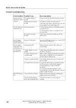
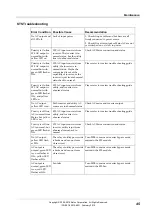
Error Condition Possible Cause
Recommendation
STS module instead of
inverter.
The inverter shelf only holds inverter modules.
Inverter module
cannot be properly
inserted
Wrong model of inverter
module.
All inverters must be the same model.
The model type that can be installed is set by the
nylon spacers. See details on page
.
Lack of input power
1. Check if input cables are all firmly connected
to power source.
2. Check if power source is switched on, or is
low in power.
No AC output and
all LEDs are off.
Mis-match of inverter
modules
Check inserted inverter modules are all the
same model.
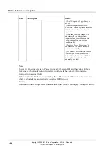
No AC output.
Both green and
yellow LEDs flash.
Inverter self-diagnosis
Inverter self-diagnosis takes a few seconds. LED
then turns to a solid green.
No AC output.
Both yellow and
red LEDs are on.
Load exceeds 125%
Reduce the load to below 100% of the total
power rating.
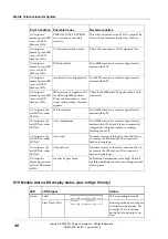
1. Input wiring is reverse
polarity.
Check input cable polarity (positive to positive,
negative to negative).
2. Output voltage is out of
operating range.
Make needed voltage adjustment to ensure that
the voltage of connected device is within the
inverter output voltage range.
3. Inverter output is shorted
Turn off the input power source to remove all
short circuits.
No AC output,
Red LED is on.
4. Negative Power Protection 1. For multi-shelf system, any jumper insertion
on JP2 connector would obstruct parallel
connections. Remove jumper from JP2
connector.
2. For single-shelf system, jumper on JP2
connector pools two inverter modules. Ensure a
jumper on JP2 connector.
1. Inverter fails to soft start
Reboot the inverter system by switching the
input power source on and off.
Red LED flashing
fast
2. Inverter temperature is
above the temperature limit.
Leave inverter idle to cool down for few
minutes.


