26
Operation and maintenance of
IZM low voltage air circuit breakers
MOELLER
www.moeller.net/de/support
10/09 AWB1230-1605
Effective October 2009
Trip actuator
The trip actuator is a small cylindrically shaped electromagnetic
device that acts mechanically to trip the circuit breaker in response
to a signal from the trip unit. In general, it is comprised of a
permanent magnet, a spring-loaded rod to produce the mechanical
tripping, and a lever for resetting the actuator after tripping occurs.
The electronic trip unit provides a pulse that counteracts the effect
of the permanent magnet, releasing the spring-loaded rod to act
mechanically. The device is reset when the circuit breaker opens.
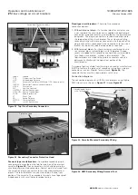
Mechanical trip flag
A red, pop-out mechanical trip indicator is an optional IZM feature.
It is located above the trip unit on the breaker’s front faceplate
(
). It operates by releasing and popping out any time the
circuit breaker trips due to an overcurrent condition.
otee:
N
The mechanical trip indicator
will not prevent the breaker from
being reclosed
.
The indicator is reset manually by pushing it back in. If the
indicator is not reset, the circuit breaker will operate normally,
but future mechanical trip indication will be lost.
An optional overcurrent trip switch (bell alarm) that operates off the
position of the mechanical trip indicator is also available. The switch
is reset when the trip indicator is reset.
On optional Digitrip models with LED cause-of-trip indicators, these
indicators should also be reset (by pushing momentarily) after the
cause of the fault has been diagnosed; this will preserve the internal
battery. On trip units equipped for communication, the LED reset
function can be performed remotely using INCOM
E
commands.
Making current release
All IZM circuit breaker trip units have a making current release
function. This safety feature prevents the circuit breaker from being
closed and latched on a faulted circuit. The non-adjustable release is
preset at a peak instantaneous current of 25 x I
n
; this corresponds to
an rms current of 11 x I
n
with maximum asymmetry.
The making current release is enabled only for the first two cycles
following a circuit breaker closing operation. The making current
release will trip the circuit breaker instantaneously, release the
mechanical (pop-out) indicator, and flash the instantaneous LED
trip indicator, if so equipped.
High-instantaneous trip option
The high-instantaneous trip option is installed in 800 to 3200A IZM
circuit breakers with a 100 kA interrupting capacity. In
general, the high-instantaneous trip is comprised of three small
air core sensors, one in each phase, which produce a signal and
transmit it back to the trip unit when the 85 kA withstand rating of
the circuit breaker is exceeded. The result is an instantaneous trip
by the circuit breaker. This high instantaneous trip option permits the
800–3200A IZM circuit breakers to be applied where a 100 kA fault
is possible, while selectivity up to 85 kA is maintained.
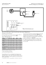
Voltage taps
On circuit breakers with Digitrip 1150 trip units, potential taps are
required to monitor the three-phase voltages. Voltage taps may
be placed on either the line (top) or load (bottom) terminals of the
breaker at the factory.
illustrates line-side voltage taps.
Figure 32. Line-Side Voltage Tap for 1150 Trip Unit
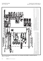
Secondary contacts and connection diagrams
A maximum of 60 secondary wiring connection points are available
on the standard frame circuit breaker (48 on narrow frame), each
dedicated to a specific function.
The wiring points are finger safe with no more than two wires
per terminal.
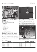
Up to two secondary contact plug-in connectors (AMP), each with
30 secondary points, are mounted on the top rear portion of the
circuit breaker. The plug-in connectors are protected by a molded
hood (
). How many connectors are mounted depends
upon a number of considerations, such as whether the circuit
breaker is electrically or manually operated and how many features
are required. When the front cover of the circuit breaker is removed,
the top of each plug-in connector is exposed. A label on each
connector identifies the wiring points (


