background image

INS #

Brand Logo  

reversed out of 

black

INS #

IB512003EN

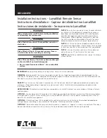
Installation Instructions - LumaWatt Remote Sensor
Instructions d’installation - Capteur de télédétection LumaWatt
Instrucciones de instalación - Sensor remoto LumaWatt

IMPORTANT: 

Read carefully before installing fixture. Retain for future reference. 

GENERAL:

 Upon receipt of the fixture, thoroughly inspect for any freight damage which should be brought to the 

attention of the delivery carrier. Compare the catalog description listed on the packing slip with the fixture label on the 

housing to assure you have received the correct material.  

SAFETY: 

This fixture must be wired in accordance with the National Electrical Code and applicable local codes and 

ordinances. Proper grounding is required to insure personal safety. Carefully observe grounding procedure under 

installation section.

APPLICATIONS: 

The remote sensor housing incorporates a LumaWatt wireless sensor available with three alternate 

control options:

OPTION 1:

 Control Relay only (CR) provides 0-10V dimming capable of controlling a maximum of five dimming drivers 

(2mA per driver), ON/OFF relay switching of a 3-amp load@120v (600W) as well as power monitoring and all the full 

benefits of LumaWatt management.

OPTION 2:

 A Switching Relay (SR) is added to the control relay to service an 8-amp to 16-amp load (depending on 

voltage). Power monitoring is not available for this option. Dimming control not available.

OPTION 3:

 The remote sensor housing can also be used as a repeater or “hopper” in which case neither of the relays 

options need to be connected. Line in power will only need to be connected for the sensor to operate.

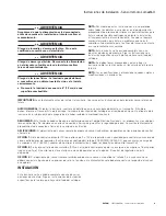
WARNING

Make certain power is OFF before starting installation 

or attempting any maintenance.

WARNING

Risk of fire/electric shock. If not qualified, consult an 

electrician.

WARNING

Risk of Electric Shock – Disconnect power at fuse or 

circuit breaker before installing or servicing.

WARNING

Risk of Personal Injury – Fixture may become damaged 

and/or unstable if not installed properly.

Do not mount luminaire within 6” of a combustible 

surface.

NOTE:

 These instructions do not claim to cover all details 

or variations in the equipment, procedure, or process 

described, nor to provide directions for meeting every 

possible contingency during installation, operation or 

maintenance. When additional information is desired 

to satisfy a problem not covered sufficiently for user’s 

purpose, please contact your nearest representative. 

NOTE: 

This fixture has been shipped complete with one 

of several mounting options. Please follow the installation 

instructions specific to the catalog part that you ordered. 

NOTE:

 Care must be taken not to set fixture down on 

optical lenses or lift the fixture in the lens area. 

NOTE:

 Specifications and dimensions subject to change 

without notice. 

Summary of Contents for LumaWatt

Page 1: ...mp to 16 amp load depending on voltage Power monitoring is not available for this option Dimming control not available OPTION 3 The remote sensor housing can also be used as a repeater or hopper in wh...

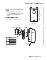
Page 2: ...in lbs Figure 3 3 Route and attach wires per wiring diagram Feed wires through the mount plate and feed wires through the pole Note N 3 of leads are provided extending outside the housing Figure 4 4...

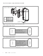
Page 3: ...gle gang wall box Figure 5 for compatible box configuration See the wiring diagrams below for both relay configurations CR dimming Figure 6 or SR non dimming Figure 7 Note N For outdoor applications o...

Page 4: ...Red 18awg Neutral In White 12 awg Neutral Out to Luminaire White 18 awg Pole or Wall Box Remote Housing Ground Green 12 awg Wiring Diagram SR Relay Option Line In Black 12 awg Line Out to Luminaire R...

Page 5: ...es options de relais n a tre connect e L alimentation n aura qu tre branch e au capteur pour qu il fonctionne AVERTISSEMENT Assurez vous que l alimentation lectrique soit HORS TENSION avant de commenc...

Page 6: ...z les selon le sch ma de c blage Faites passer les c bles par la plaque de montage et acheminez les par le poteau Remarque R Une longueur de 91 44 cm 3 pi de fils est fournie l ext rieur du bo tier Fi...

Page 7: ...rt NEUTRE Ligne Blanche COURANT Ligne Noire Install au mur Le bo tier peut s installer sur un mur directement sur un bo tier mural standard Figure 5 pour une configuration compatible Consultez le sch...

Page 8: ...nc Sortie neutre vers le luminaire AWG 18 blanc Poteau ou bo tier mural Bo tier de t l d tection Mise la terre AWG 12 vert Sch ma de c blage de l option de relais SR Alimentation AWG 12 noir Sortie ve...

Page 9: ...o tambi n puede usarse como un repetidor o saltador en cuyo caso no se deber conectar ninguna de las opciones de rel La tensi n en la alimentaci n solo deber conectarse respecto del sensor que operar...

Page 10: ...aje y luego a trav s del poste Nota N Se incluyen 3 0 91 cm de cables que se extienden por fuera del alojamiento Figura 4 4 Inserte los cables en el poste a medida que coloca el alojamiento en la plac...

Page 11: ...amiento para una mayor protecci n impermeable Brazo de montaje ajustable para pared Figura 4 Cable neutro del lado de la alimentaci n con cable blanco de la luminaria Cable de tensi n de l nea del lad...

Page 12: ...SR se muestra cableado e instalaci n de caja de salida nica Tornillos de montaje del alojamiento Leng eta del gancho de amarre CONEXI N A TIERRA VIVO ENTRADA VIVO carga NEUTRO Figura 7 12 AWG Verde C...

Page 13: ...13...

Page 14: ...14...

Page 15: ...15...

Page 16: ...odas las marcas comerciales son propiedad de sus respectivos propietarios Product availability specifications and compliances are subject to change without notice La disponibilit du produit les sp cif...

Reviews: