INM831B Rev 4
6
Typically a user might expect:
IS applications - 0.5km
Non-IS applications - 1.5km
However, with good quality, screened, twisted-pair cable and an
environment that is relatively free from RFI, distances up to 3km have
been achieved.
4.4.2
IS applications
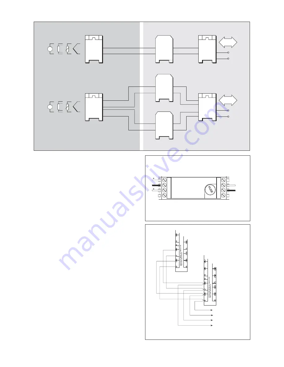
For IS applications, the data/power connection must be via a
galvanic isolator and so an MTL3052 isolator is connected in-line in
the safe area (see Figure 10). One MTL3052 is required for each
separate highway.
The –ve and +ve terminals of the H1 (1 & 2) should be connected to
the corresponding –ve and +ve terminals of the MTL3052 (6 & 7
respectively)located in the safe area. If a second highway is required
for redundancy, connect the H2 (terminals 4 & 5) to a second
MTL3052, observing correct polarity.
4.5
MTL3052 digital isolator
The MTL3052 (figure 11) features two ouput circuits: one with a 15V
180
safety description (terminals 7 & 8), and an alternative 15V
100
circuit (terminals 5 & 6), which can be used if higher loop
resistances need to be accommodated; for example, when surge
protectors are incorporated in the data highways. The maximum loop
impedance per highway for different applications is shown in Figure 11.
NOTE: In a dual highway configuration, if terminals 5 & 6
are used for both highways, the multiplexer transmitters
are restricted to use in IIB atmospheres.
4.6
Multi-transmitter connections
Connect the highway(s) to a receiver for one MTL831B transmitter as
in (e). (figure 12)
Connect one or two data highways between output terminal pairs H1
(terminals 1 and 2) and/or H2 (terminals 4 and 5) to the equivalent
terminals on a second MTL831B transmitter (terminals 3 and 4 for
H1and terminals 1 and 2 for H2).
NB: two MTL831B transmitters or one MTL831B plus one MTL831 or
two MTL832 transmitters can be linked in this way.
Hazardous area
Safe area
Serial data-link
to host computer
mV
THCs, RTDs
or mV sources
+
5 or 7*
2
+
Highway 1 or 2
6
3
mV
THCs, RTDs
or mV sources
RS485
2 or 5
& &
1 4
35 or 37
36 or 38
22
+
24V dc
23
MTL831B
transmitter
MTL3052
interface unit
MTL838B-MBF
receiver
5 or 7*
2
6
3
Serial data-link
to host computer
2 +
+
Highway 1
1
5
MTL3052
interface unit
35
36
RS485
+
22
+
Highway 2
+
4
37
38
24V dc
23
MTL831B
transmitter
5 or 7*
2
MTL838B-MBF
receiver
6
3
Figure 10
- Single and dual highways in IS applications
MTL3052
interface unit
* Terminal 5: low resistance
Terminal 7: high resistance
-
+
12
11
31
32
+
12
-
-
113
+
10
9
33
34
Transmitter 2
+
11
-
-
114
+
8
35
00 -
7
Spare
6
5
36
-
115
+
+
H2
-
37
+ 00
38
14
-
111
+
14
29
39
-
4
Spare
3
2
116
+
13
+
13
40
41
-
30
-
112
+
+
H1
-
12
11
31
-
32
1OOR
+
1
42
+
12
-
-
113
+
10
9
33
34
+
-
11
0ne or both
highways between
transmitters can be used
-
8
00 -
7
Spare
6
5
+
H2
114
+
35
36
-
115
+
Transmitter 1
37
+ 00
38
39
-
-
4
Spare
3
2
+
H1
116
+
40
41
-
1OOR
-
0ne or both
+
highways to
1
42
receiver can be
used
Highway1 to
receiver
Highway 2 to
receiver
Figure 12
- Multiple transmitter applications
Maximum loop impedance per highway
Terminal 7/8 – 50
Ω
Terminal 5/6 --130
Ω
Non-IS apps. – 300
Ω
MEASUREMENT TECHNOLOGY LTD.
+
MTL3000 range
Terminals internally
6 and 8 are linked
Terminals 1 and 4
are unused
Figure 11
- MTL3052 terminals
5
6
7
8
4
3
2
1
M
T
L8
31
B
A
M
T
L8
31
B
A
na
lo
gu
e
m
u
lti
p
le


