background image

10

INM MTL831C Rev 7

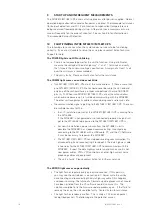
START UP AND INFREQUENT MEASUREMENTS

The MTL831C/MTL831C-PS enters a startup process after power is applied.  Normal 
operation begins about 60 seconds after power is applied.  Thermocouple resistances 
(for burnout detection) and CJC (Cold Junction Compensation) temperatures are 
being measured frequently during startup.  Afterwards these measurements are 
made infrequently (on the order of minutes).  See section 4.5 for information on 
Thermocouple Burnout Detection.

10 

FAULT-FINDING IN THE MTL831C/MTL831C-PS

The following are some tips when the system does not seem to be functioning 
correctly.  If you are still unable to solve the issue, please contact Eaton Technical 
Support for help.

The POWER light is not ON or blinking


•  There is not adequate power for the unit to function.  Using a Voltmeter,  


measure the voltage at the data highway “+” and “-“ terminals and verify  


that it meets the minimum voltage specification.  A margin of at least 1 volt  


over the minimum is recommended.


•  The unit is faulty.  Please contact Eaton for further assistance.

The COMM light comes on and does not blink

  • Two 

MTL831C/MTL831C-PSs are at the same address.  If there is more than  

  one 

MTL831C/MTL831C-PS (there should never be more than 2), one and  


only one of them should have a jumper wire between the two ADDRESS  


pins (A, S).  When two MTL831C/MTL831C-PSs are at the same address  


whichever one powers up first will be communicating with the MTL838C.   


The other unit recognizes its address already being used and remains idle.


•  No communication signal is getting to the MTL831C/MTL831C-PS.  There can  


be multiple reasons for this:


•  In an IS installation, power for the MTL831C/MTL831C-PS is coming from  


  the MTL5553.  


  If the MTL838C is not powered or not connected properly no signal will  


  get to the MTL5553 to be passed to the MTL831C/MTL831C-PS is.


•  For non-IS installations, power comes from the MTL838C, so it is  


  possible the MTL838C has stopped communicating.  Investigate by  


  connecting to the MTL838C with a USB cable, PC, and the PC Software.   


  It may be necessary to repower the MTL838C.

    • The 

MTL831C/MTL831C-PS has stopped receiving communication.  Try  


  disconnecting it and reconnecting it to reboot it. The data highway cable  


  is too noisy for the MTL831C/MTL831C-PS to communicate with the  


  MTL838C.  Inspect the data highway cable run and make sure it is not  


  near power cables, VFDs, VFD controllers, or other high current noise  


  producing cables and equipment.


•  The unit is faulty.  Please contact Eaton for further assistance.

The ERROR light comes on periodically


•  The light flashes regularly every one or two seconds.  If this persists,  


you may see the unit reboot – see section 6.1.  Power cycle the unit by    


disconnecting and reconnecting the data highway cable if this happens    


and keeps recurring. The failure of a firmware update process which would  


have been initiated from the PC software could also cause this.  The  


solution would be to try the firmware update process again.  If that fails to  


remedy the issue, the unit could be faulty.  Contact Eaton for assistance.


•  The light flashes randomly or often.  This is likely a CRC error on packet  


receipt (bad packet).  The following are the potential causes:

Summary of Contents for MTL831C

Page 1: ...MTL831C MTL831 PS Analog Transmitter September 2022 INM MTL831C Rev 7 Instruction manual with Ex Safety Instructions 503 215 503 548 MTL intrinsic safety solutions...

Page 2: ...RATION OF CONFORMITY A printed version of the Declaration of Conformity has been provided separately within the original shipment of goods However you can find a copy of the latest version at http www...

Page 3: ...5 5 3 Sensor inputs 5 5 4 RTD inputs 5 5 5 THCs and mV inputs 5 5 6 THC Burnout Detection 6 5 7 Mixed Inputs 6 5 8 Data highway 6 5 9 Transmission distances 6 5 10 IS applications 7 5 11 Multi transmi...

Page 4: ...his manual and the product datasheet Ensure installation and operating personnel have received adequate training for this task Ensure that any operating instructions are fully understood by the person...

Page 5: ...ing to the safety of their installations and these requirements should also be met 1 ABOUT THIS MANUAL The purpose of this manual is to provide the user with information on the installation connection...

Page 6: ...to support different control system interfaces See the Components and Accessories section for part numbers One or two MTL831C MTL831C PSs may be connected to a single MTL838C The MTL838C provides a M...

Page 7: ...rtical plane on vertical or horizontal DIN rail to meet accuracy specifications Heat sources causing a temperature gradient in the MTL831C MTL831C PS may cause accuracy outside of specifications The u...

Page 8: ...pins sets the address to 2 Either is valid for a system with only one MTL831C MTL831C PS connected to the MTL838C When two MTL831C MTL831C PSs are connected to a single MTL838C they must be addressed...

Page 9: ...r damage the MTL831C MTL831C PS If sensors must be earthed they should be located close to each other to avoid differences in earth potential 5 4 RTD inputs The 16 channels can be configured for 2 3 o...

Page 10: ...data highway connection is also the source of DC power for the MTL831C MTL831C PS It is important that the polarity of the wiring on the and terminals is correct A shielded twisted pair wire is recom...

Page 11: ...nect the data highway to a receiver for MTL831C MTL831C PSTransmitter 1 as in diagram below Connect the MTL831C MTL831C PSTransmitter 1 data highway S and terminal to the equivalent terminals on a MTL...

Page 12: ...TL831C MTL831C PS transmitter and the MTL838C is tied to the S terminal of the Data Highway port on the MTL838C The S terminal is internally connected to the GROUND terminals of the MTL838C The GROUND...

Page 13: ...See the PC software or Modbus manuals for information on configuring sensors 8 LED INDICATORS There are 2 LEDs to indicate the health and status of the unit The following are their meanings POWER Whe...

Page 14: ...ing used and remains idle No communication signal is getting to the MTL831C MTL831C PS There can be multiple reasons for this In an IS installation power for the MTL831C MTL831C PS is coming from the...

Page 15: ...way cable Use the PC software to check the diagnostic information Try rebooting each device connected to the data highway one at a time Contact Eaton for assistance if the source of the issue cannot b...

Page 16: ...12 INM MTL831C Rev 7 11 FM ATEX and IECEx Information...

Page 17: ...13 INM MTL831C Rev 7...

Page 18: ...14 INM MTL831C Rev 7...

Page 19: ...15 INM MTL831C Rev 7...

Page 20: ...16 INM MTL831C Rev 7...

Page 21: ...17 INM MTL831C Rev 7...

Page 22: ...18 INM MTL831C Rev 7...

Page 23: ...19 INM MTL831C Rev 7 12 CCC INFORMATION...

Page 24: ...20 INM MTL831C Rev 7...

Page 25: ...21 INM MTL831C Rev 7...

Page 26: ...n which the units are mounted have not been degraded by the introduction of harmful materials h access lids and doors to protective enclosures and cabinets are correctly secured 13 2 Disposal Product...

Page 27: ...ff Old Mahabalipuram Road Sholinganallur Chennai 600 119 India Tel 91 0 44 24501660 24501857 Fax 91 0 44 24501463 E mail mtlindiasales eaton com ITALY MTL Italia srl Via San Bovio 3 20090 Segrate Mila...

Reviews: