18
Instructional Booklet
IB02102006E
Effective May 2011
Type MVS (previously WLI)
metal-enclosed switchgear—
4.76 kV, 15.0 kV, 27.0 kV, and 38.0 kV
eaton corporation
www.eaton.com
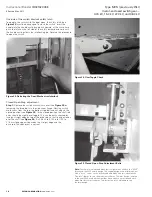
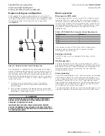
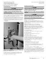
Override of the switch interlock safety latch
To operate the switch with the door open, the safety latch (see
Figure 23
) must be disengaged . To close the switch, insert the
handle into the handle casting and push upward, at the same time
push the latch on the left side of the safety barrier downward until
the handle casting clears the interlocking pin . Reverse this procedure
to open the switch .
Figure 23. Defeating the Door/Mechanism Interlock
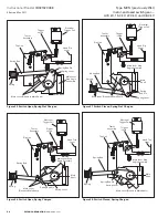
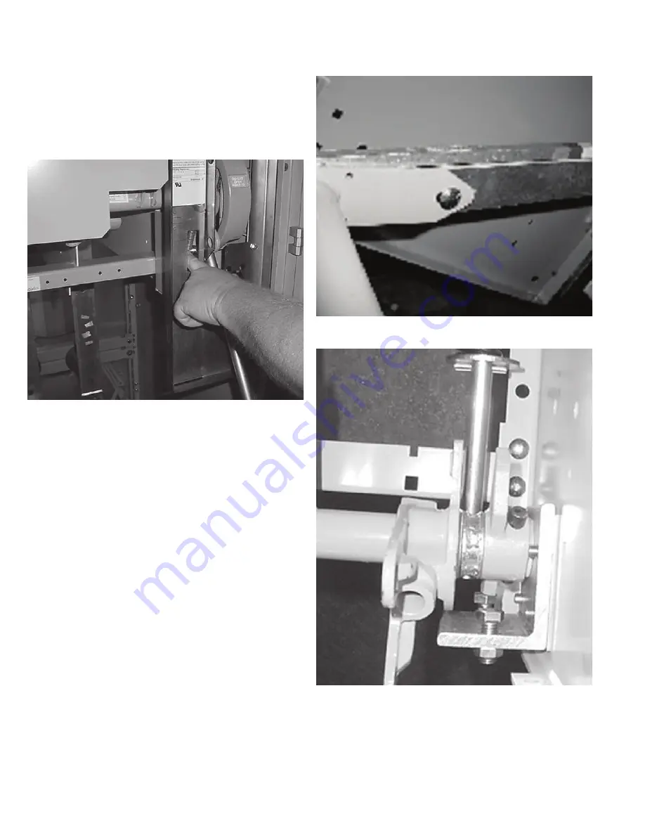
Closed-Open-Stop adjustment
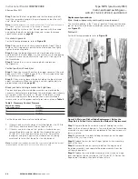
Step 1e:
Remove the switch mechanism cover (see
Figure 23
) by
removing the three bolts in the side sheet flange . Viewing switch
mechanism from the top, the bottom stop bolt and nut adjusts the
closed position (see
Figure 25
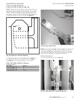
) . In the closed position, the shaft rod
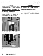
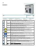
ends should be slightly over toggle . This can be easily checked by
laying a straight edge on top of the drive rod so that its end extends
over the shaft (see
Figure 24
) . If a 0 .0625 to 0 .125 inch (1 .59 to
3 .18 mm) gap appears between the straight edge and the
drive rod, the adjustment is correct .
Figure 24. Over Toggle Check
Figure 25. Closed-Open-Stop Adjustment Bolts
otee:
N
There are two blade and break jaw configurations used on the “MVS”
(previously the WLI) switch design . The original design used a flat break jaw
with a “hook” cutout on the bottom and each blade had two indentations
(“bullets”) that bore onto the break jaw surfaces . The later design, initiated
in the year 2000, used a break jaw that has a ridge on each side and each
blade has flat contact surfaces . This instruction book will address only
the later design .


