19
Instructional Booklet
IB02102006E
Effective May 2011
Type MVS (previously WLI)
metal-enclosed switchgear—
4.76 kV, 15.0 kV, 27.0 kV, and 38.0 kV
eaton corporation
www.eaton.com
Step 2e:
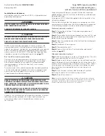
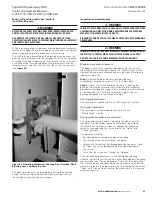
Check to see that the blades are fully closing . To do this,
measure the distance from the end of the break jaw to the front
edge of the blade . This dimension should be 0 .10 to 0 .30 inches
(2 .54 to 7 .62 mm) . Should adjustment be required, loosen the
bolt holding the drive rod to the shaft and adjust the blade travel .
Re-tighten the bolt to 25 ft-lbs (33 .90 Nm) (see
Figure 27
) .
Figure 26. Break Jaw and Blade Clearances
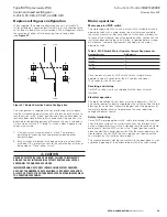
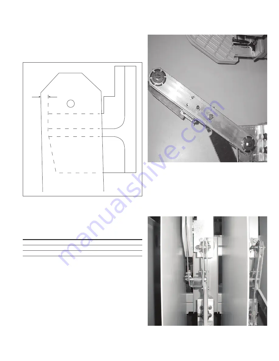
In the “Open” position, the clearance between the edge of the
main blade and the break jaw should be as listed in
Table 4
(see
Figure 27
) . The top stop bolt adjusts this dimension .
Table 4. Main Blade to Break Jaw Clearances
open Gap Dimension
inches (mm)
kV class
6.625 ± 0.125 (168.28 ± 3.18)
4.76
6.625 ± 0.125 (168.28 ± 3.18)
15
11.00 ± 0.125 (279.40 ± 3.18)
27 or 38
0.125–0.281
Figure 27. Open Gap Distance
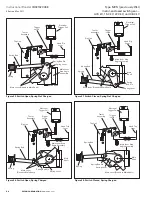
Step 3e:
If the switch is equipped with key interlocking, care must be
taken when replacing the switch mechanism cover to ensure that
it is properly repositioned . Elongated holes in the MVS side sheet
allow for vertical adjustment . The key interlock bolt must clear the
“Open-Closed” indicating cam casting when retracted .
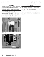
Main blade alignment
For the following procedure, refer to
Figure 28
.
Figure 28. Main Blade and Flicker Blade Alignment


