23
Instructional Booklet
IB02102006E
Effective May 2011
Type MVS (previously WLI)
metal-enclosed switchgear—
4.76 kV, 15.0 kV, 27.0 kV, and 38.0 kV
eaton corporation
www.eaton.com
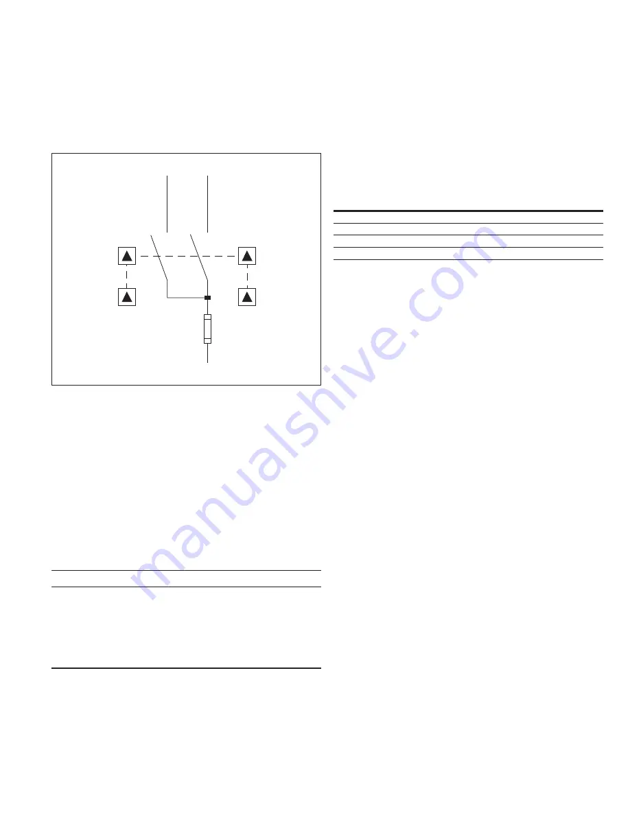
Duplex switchgear configuration
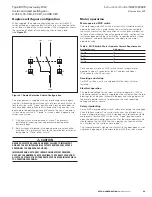
When supplied, the duplex configuration consists of two MVS
switches feeding a common bus, which in turn is connected to the
set of fuses in one of the switch sections . This arrangement allows
the selection of either of two incoming lines to feed a load
(see
Figure 31
) .
Figure 31. Duplex Selective Switch Configuration
This arrangement is supplied with key interlocking for safe opera-
tion . Key interlocking normally consists of a lock on each switch to
lock the switch in the “Open” position and a lock on each door to
lock each door closed . Each lock is keyed alike . Only one key is to
be available to operating personnel . Because the key is retained in
its lock when a switch is “Closed” or when a door is opened, two
things are ensured:
1.
Only one switch may be closed at a time . This prevents
paralleling of incoming lines and prevents opening either
enclosure door .
2.
Both switches are locked in the open position to unlock either
main door . This prevents access to the common bus or fuses or
being able to “Close” either switch .
CAUTION
HAzARD OF ELECTRICAL SHOCK OR BURN. FAILURE TO IMPLEMENT
AND USE THE KEy INTERLOCKING SySTEM PROVIDED WILL EXPOSE
PERSONNEL TO DANGEROUS VOLTAGES.
IMPLEMENT AND USE THE KEy INTERLOCKING SySTEM PROVIDED.
USE ONLy THE NUMBER OF KEyS REQUIRED FOR CORRECT OPERATION.
ALL EXTRA KEyS MUST BE EITHER DESTROyED OR MADE INACCESSIBLE
TO OPERATING PERSONNEL.
Line
LO
LO
LD
LD
Load
Line
Motor operation
Motor-operated MVS switch
The motor-operated MVS switch is essentially a standard manually
operated switch with a motor driven linear actuator connected to
the switch mechanism . Because all basic switch parts are identical
to those of the standard, manually operated switch, sections of this
instruction book pertaining to installation, inspection before startup,
maintenance, and parts replacement also apply to the motor
operated switch .
Table 6. MVS Switch Motor Operator Current Requirements
nominal Voltage
e/r amperes
120 Vac
3.0
24 Vdc
7.0
48 Vdc
3.5
125 Vdc
1.5
Time to open or close an MVS switch with an integral motor
operator is about 5 seconds for the AC versions and about
10 seconds for the DC versions .
Receiving and startup
For MVS switches, units are shipped with the linear actuator
installed .
Electrical operation
The preferred voltage for the linear actuator to operate is 120 Vac,
and control power is normally supplied by the customer . See the job
drawings for an electrical schematic diagram and wiring diagram of
the motor operator circuitry to determine the actual operating
voltage and power source .
Safety interlocking
For an MVS motor-operated switch, safety interlocking is based upon
a key interlock system . The switch mechanism key interlock must
have an integral electrical switch . Extending the interlock bolt would
mechanically lock the MVS switch in the “Open” position, would
open the electrical control power circuit for the motor operator, and
would release the key . With the key, a person can then unlock the
key interlock on the switch enclosure door .
This scheme prevents closing the switch with the door open as well
as prevents opening of the enclosure door with the switch closed .


