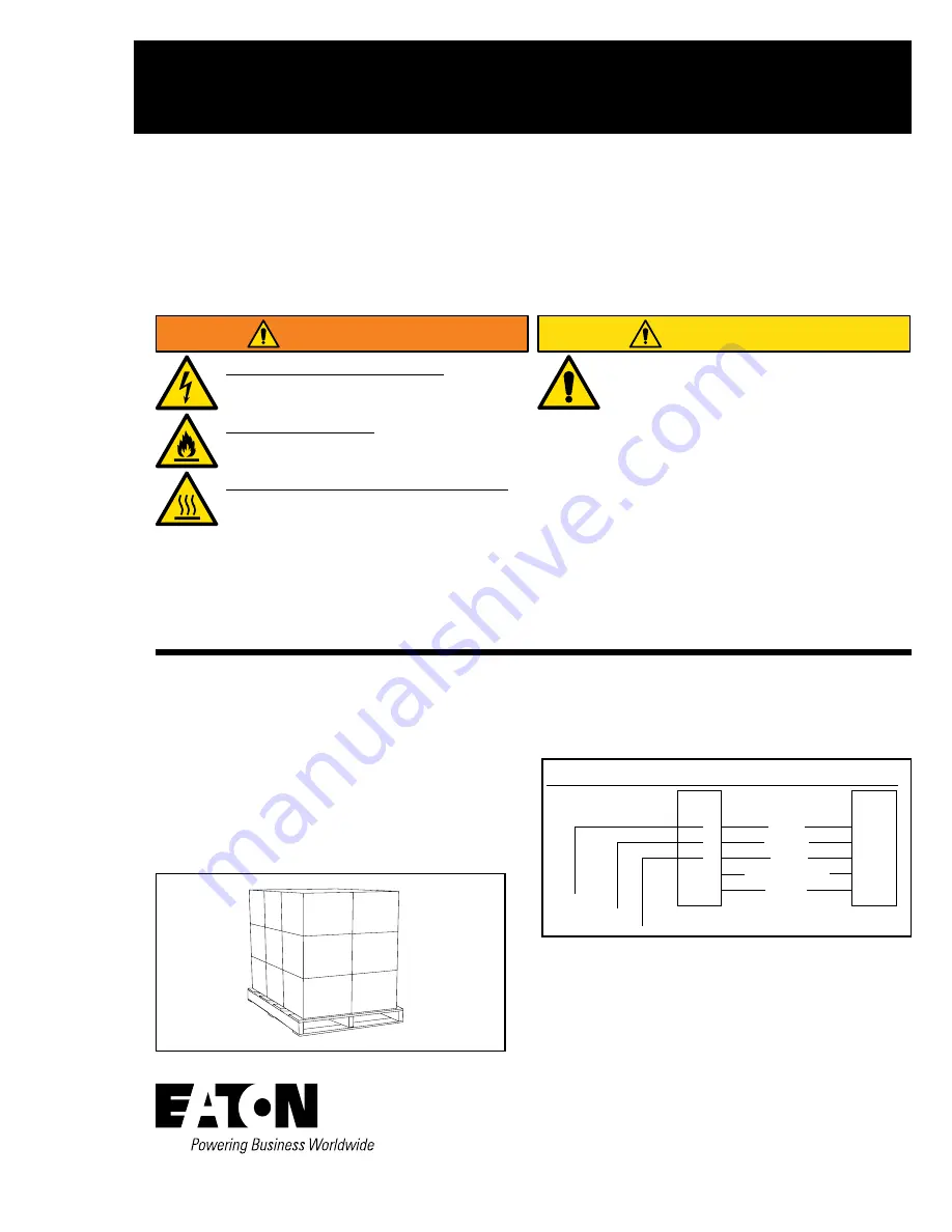
Risk of Fire and Electrical Shock- MWS must
be installed by qualified personnel. If not
qualified, consult an electrician.
Risk of Electric Shock- Disconnect power at
fuse or circuit breaker before installing or
servicing.
Ensure both latches are securely fastened-
Unlatched connections can separate causing
arcing and overheating of the connectors.
WARNING
IMPORTANT:
Read, understand and follow all MWS
safety and installation instructions. Retain for future
reference.
NOTICE:
Installation must comply with all applicable
national and local codes. Manufactured wiring systems
covered by Article 604 of the National Electrical Code.
NOTICE:
Do not use any MWS component for other
than it’s intended purpose.
NOTICE:
Do not tamper with the internal wiring of any
MWS component or physically modify in any way.
NOTICE:
Starter fitting/starter fixture cable is
the starting point of the MWS system. All MWS
components attached to the system will be energized.
Cap all unused connector openings.
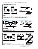
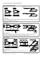
Installation Instructions – MWS 0-10V Dimming
Instructions d’installation – Système de câblage modulaire de
gradation 0 à 10 V
Instrucciones de instalación – Atenuación MWS 0-10V
IMPORTANT:
Save installation instructions for future changes.
IB519111EN
MWS
Failure to comply with these instructions may result in
death, serious bodily injury and property damage.
DISCLAIMER OF LIABILITY: Eaton assumes no liability
for damages or losses of any kind that may arise
from the improper, careless, or negligent installation,
handling or use of this product.
INSTALLATION
1. Standard carton size 14”W x 14”L x 12”H
Half carton size 14”W x 14”L x 6”H.
2. Each carton label list component cat. no. quantity,
length voltage with photograph.
3. Standard pallet size: 32”W x 46”L x 42”H
Max. 18 cartons per pallet. Pallets are shrink
wrapped by Cooper.
120V/277V/347V
Grey
Purple
Black
White/Neutral
Green
0-1
0V Dimming
5
4
3
2
1
5
4
3
2
1
MWS Standard Contact Configuration
CAUTION
Only use with compatible MWS 0-10V
components.
0-1
0V Dimming
12/2G
10/2G


