2
Consult MWS Installation, Application and Specification Manual for
additional comprehensive system information.
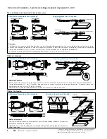
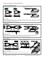
Starter Fitting/Starter Cable
MWS
IB519111EN
Installation instructions
Installation Instructions – MWS 0-10V Dimming
System View (not to scale)
Dimensional and Mounting Details
Starter (ST)
Converts conventional wiring to MWS. Branch circuits are fed from the panel to a junction box with conduit and wire. The Starter is
mounted to the junction box with a 1/2” threaded lock nut connector. Circuits are then connected to the appropriate leads of the Starter.
Starter Cables have 9’, 15’ or 21’ of MC cable.
Fixture Cable
System View (not to scale)
Dimensional and Mounting Details
Fixture Cable (FC)
Feeds power to fixtures and allows circuits to be carried through to other fixtures. Locks into 1/2” KO of access plate, fixture body or
J-box. The unit adds 7/8” to overall height of the fixture.
Typical MWS Wiring System Application shown utilizing Fixture Cable (FC).
Extender Cables
System View (not to scale)
Dimensional and Mounting Details
Extender Cable (EC)
Supplies power between MWS components. Cables connect together without use of couplers.
Typical MWS Wiring System Application shown utilizing Extender Cable (EC).
STARTER FITTING
STARTER CABLE
Unit with no cable
Unit with no cable
Starter
Starter Cable
Fixture Cable
Fixture Cable
Extender or Fixture Cable
Extender or Fixture Cable
Front
3/4”
[19mm]
3/4”
[19mm]
4-3/8”
[112mm]
1-7/8”
[47mm]
4-3/8”[112mm]
4-3/8”[112mm]
3/4”
[19mm]
5/8”
[16mm]
4-3/8”
[112mm]
5/8”
[16mm]
1-7/8”
[47mm]
4-3/8”
[112mm]
3/4”
[19mm]
4-3/8”
[112mm]
Front
Top
Front
Fixture Cable
Fixture Cable
Fixture Cable
Quick Connect
Front
Front
Front
Starter
Circuit T
Extender Cable
Switch Drop
Fixture Cable
Fixture
Cable
Fixture
Cable
Fixture Cable
Extender
Cable
Extender Cable
Drop SO Cord
Switch
Drop
Top
Side
Top
Side
Top
Side
Side


